The SWIR0503 series cameras are equipped with Sony IMX991 SenSWIR InGaAs sensor, featuring a pixel size of 5 µm and a resolution of 0.33 MP, which ensures high sensitivity and low noise performance. Supporting interfaces including USB3, GigE, CoaXPress, and CameraLink, they are suitable for applications such as high-speed inspection, laser beam monitoring and scientific experiment imaging.
| Features |
| 400–1700 nm spectral response,5 µm Pixel size |
| Multiple interfaces:USB3.0 / GigE / CoaXPress / CameraLink |
| TEC cooling |
| Global shutter, high-speed acquisition |
| 12-bit (8/10/12-bit optional for specific models) |
| Hardware ROI & external triggering |
| 512MB cache (Model-Dependent) |
| CE/FCC Cerifcation,Multi-platform SDK |
AttosView supports Windows® 7 (64-bit),10 and 11 operating systems.
The SDK supports development languages such as C/C++, C #/VB.net, Python, Java, etc,
Third-party support including LabVIEW, MATLAB, Micro-Manager, DirectShow, and TWAIN.
SWIR cameras are widely used across various fields, including industrial inspection, machine vision, material sorting, food testing, scientific research, medical diagnosis, security monitoring, process control and transportation. They perform particularly well in material analysis, moisture detection, penetration through haze/smoke, and nighttime monitoring.
| Common Specifications | |
| Sensor Model | Sony IMX991 InGaAs |
| Spectral Range | 400-1700nm |
| Pixel Size | 5um*5um |
| Sensor Size | 1/4″ |
| ADC | 12Bit/8Bit |
| Image Buffer | 512Mb |
| Conversion Gain | 42.29e/ADU |
| Dynamic Range | 59.7db |
| Readout Noise | 176.7e |
| Full Well Capacity | 173.23ke |
| Maximum SNR | 52.39dB |
| Sensitivity | 121mV/(lx·s) |
| Dark current | 383e(0),510e(10),638e(20) |
| Gain range | 1-15x |
| Exposure Time Range | 15us-60s |
| Shutter Mode | Global Shutter |
| Digital I/O | 1 channel of optically isolated input 1 channel of optically isolated output 2 channels of non-isolated input/output ports |
| Data Format | 12Bit/8Bit |
| Cooling performance | 25°C below ambient temperature |
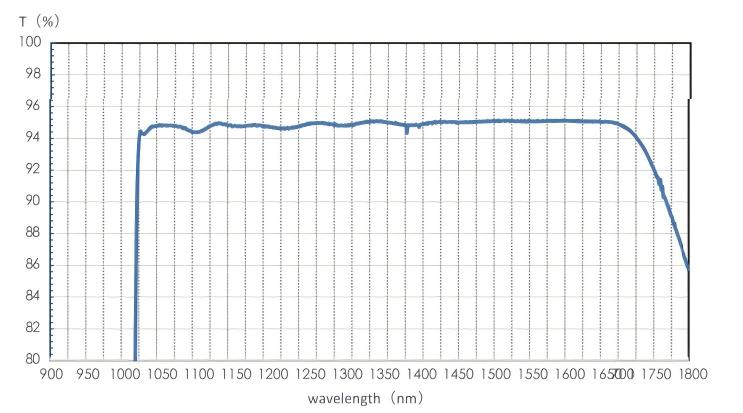
| Optical Filter | 400-1800nm (Standard); 1030-1800nm (Optional) |
| CRA | 2.35° |
| Power consumption | <25W(Refrigeration) |
| Temperature | Working temperature: -20~60℃, Storage Temperature: -40~85℃ |
| Humidity | 20%-80%,no condensation |
| Weight | <390g |
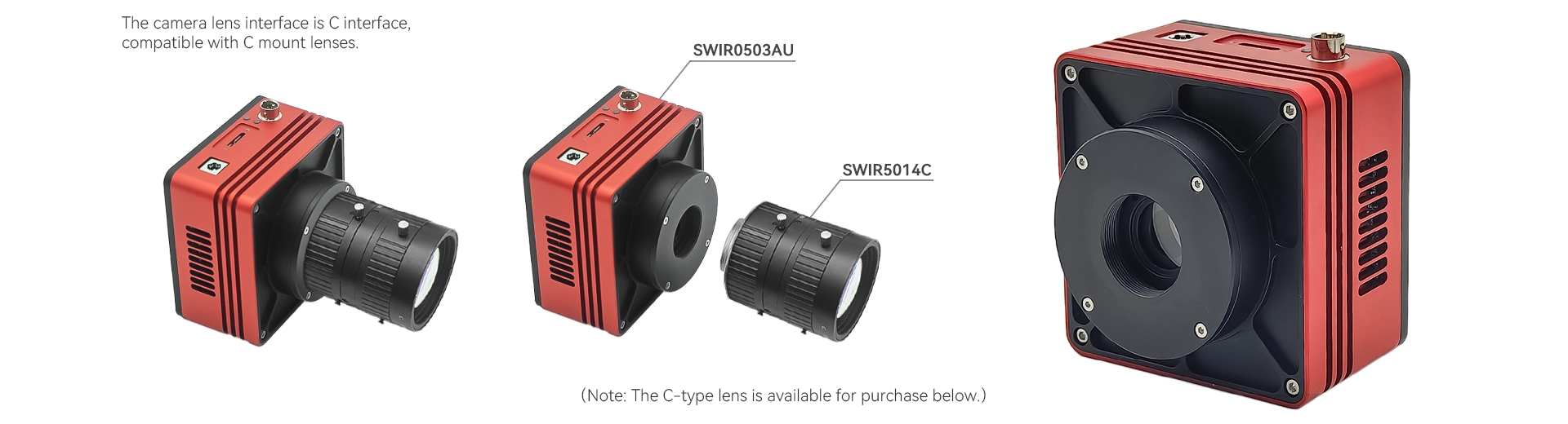
| Lens mount | C-mount |
| Operating system | Win32/WinRT/Linux/macOS/Android |
| Certification | CE,FCC |
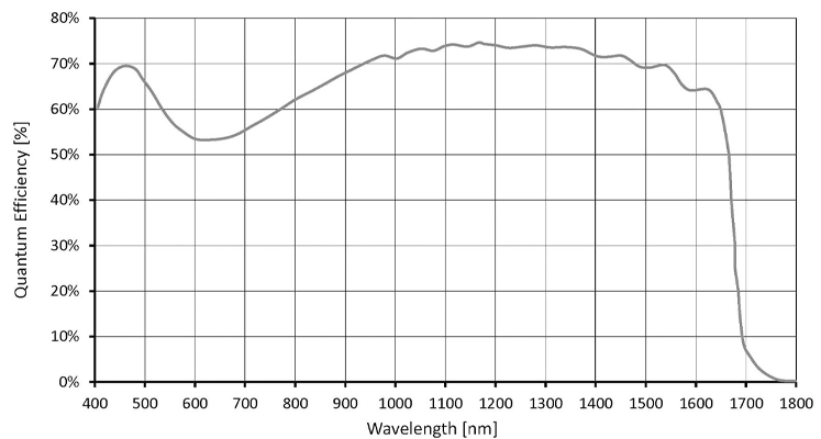
Quantum Efficiency Curve
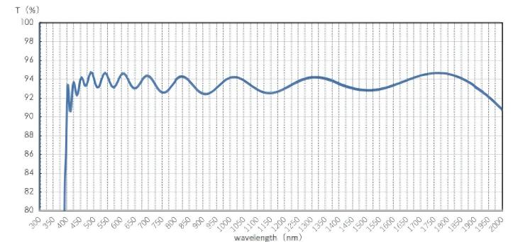
Standard filter: Long wave pass filter LPF390H transmittance curve
| Parameter | Specification |
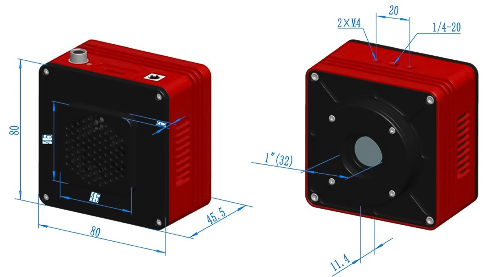
| Size | 80*80*45.5mm |
| Mount | C mount |
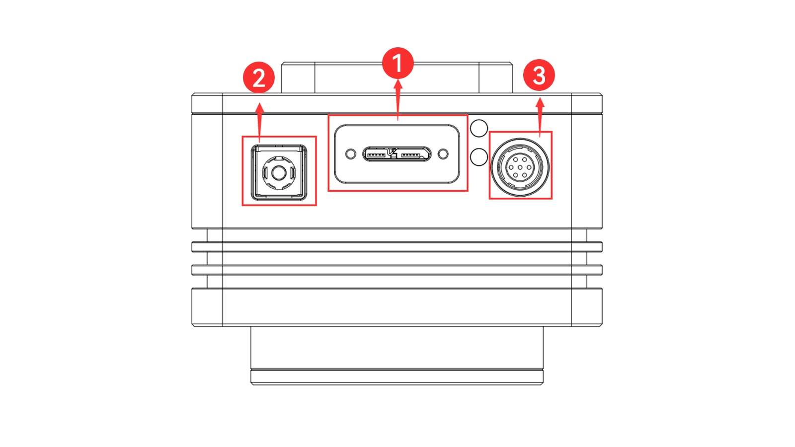
| Item | Specification |
| 1 | USB3.0 port |
| 2 | DC 12V power |
| 3 | External IO connection port |
| Parameter | Specification |
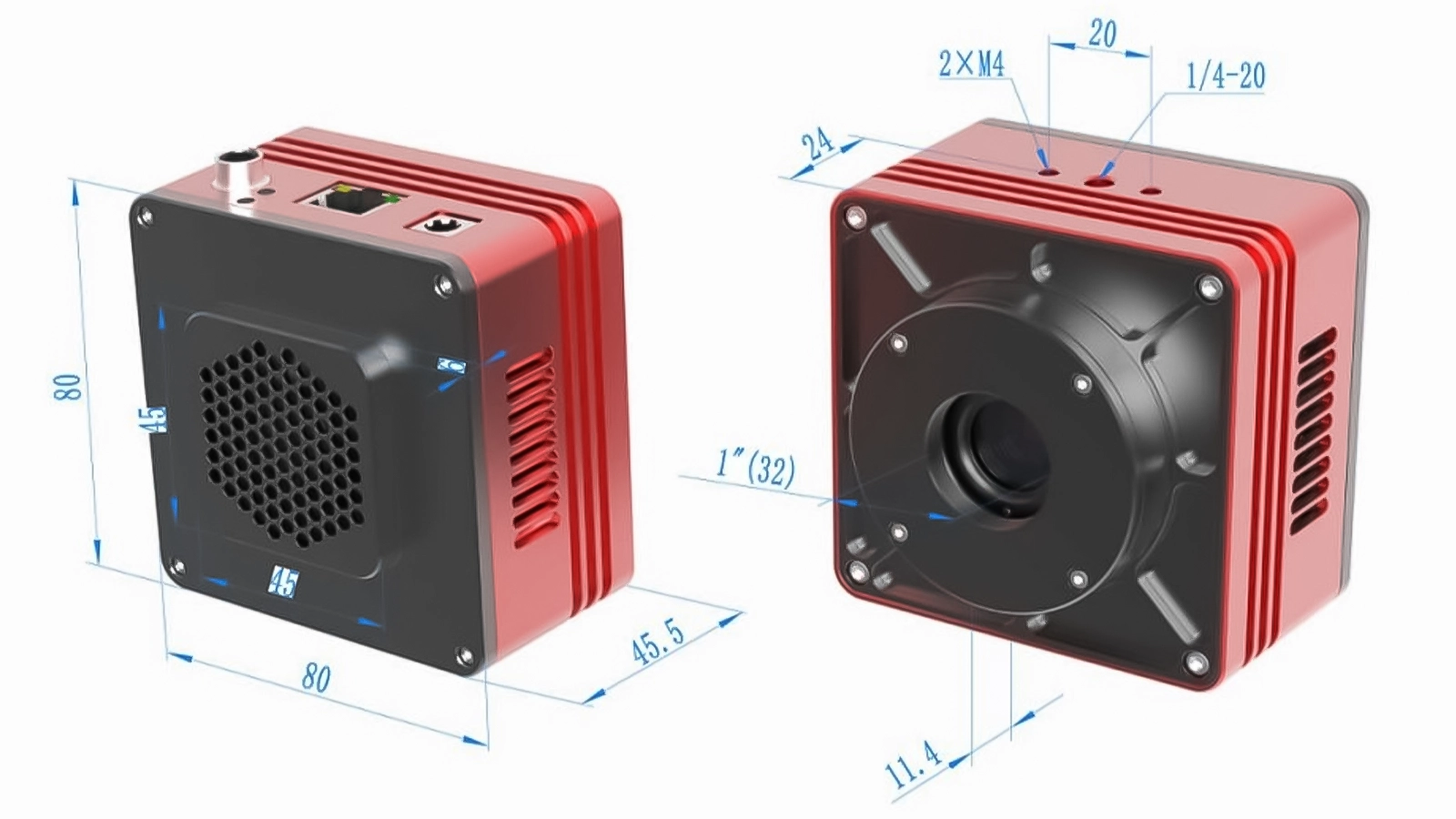
| Size | 80*80*45.5mm |
| Mount | C mount |
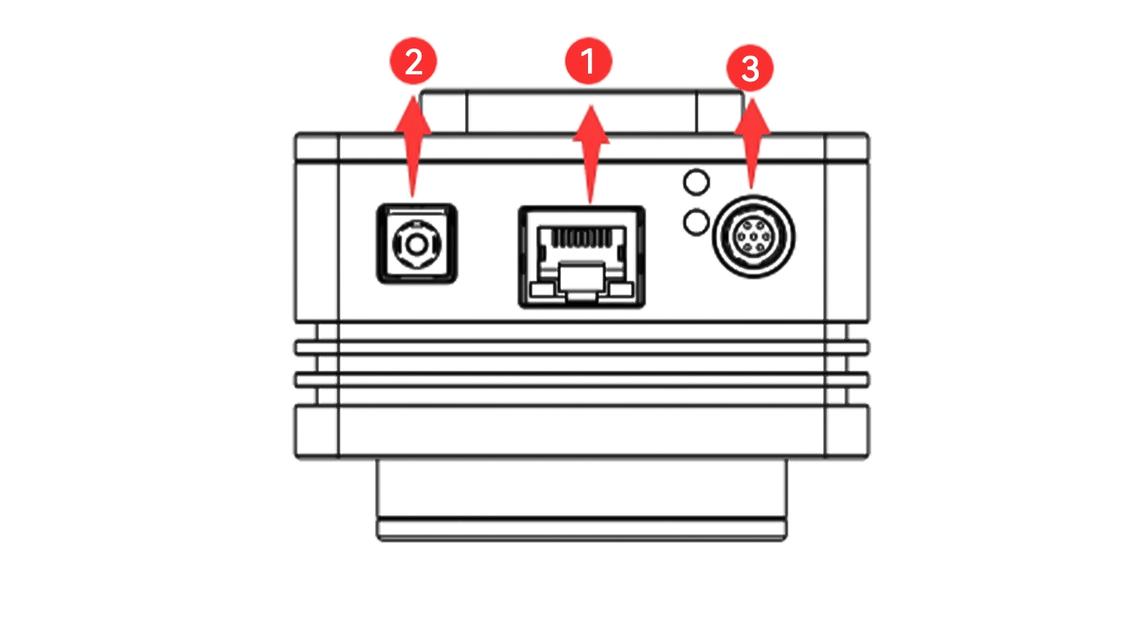
| Item | Specification |
| 1 | GigE port |
| 2 | DC 12V power |
| 3 | External IO connection port |
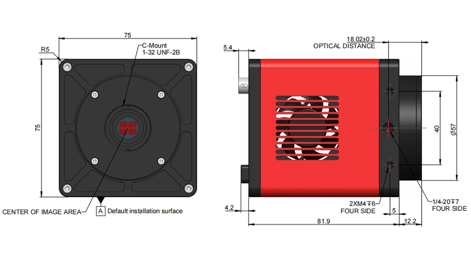
| Parameter | Specification |
| Size | 75*75*81.9mm |
| Mount | C mount |
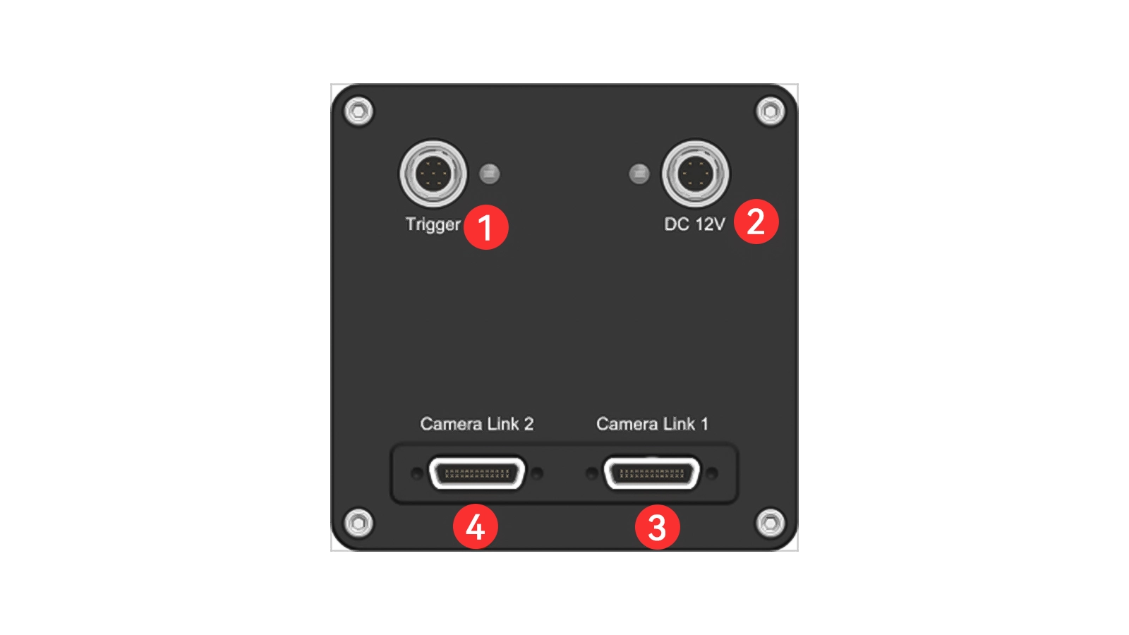
| Item | Specification |
| 1 | External IO connection port |
| 2 | DC 12V power |
| 3 | CameraLink1 |
| Table1: USB port, GigE port, CL port refrigerated camera pin signal definitions | |||||
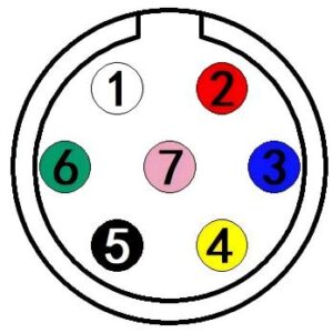 | Color | Pin | Signal | Description of the signal | |
| White | 1 | GDN | Direct-coupled signal ground | ||
| Red | 2 | 12V | 12V DC power input | ||
| Blue | 3 | OPTO_GND | Opto-isolated signal ground | ||
| Yellow | 4 | DIR_GPIO0 | Direct-coupled General Purpose I/O (Software configurable input/output) (line2) | ||
| Black | 5 | DIR_GPIO1 | Direct-coupled General Purpose I/O (Software configurable input/output) (line3) | ||
| Green | 6 | OPTO_IN | Opto-isolated input signal (line0) | ||
| Pink | 7 | OPTO_OUT | Opto-isolated output signal (line1) | ||
Opto-isolated input circuit (line0)
Logic 0 input level: 0~2.2VDC (OPTO_IN pin)
Logic 1 input level: 3.3~24VDC (OPTO_IN pin)
Maximum input current:30mA
When the input level is between 2.2V and 3.2V, the circuit operation state is uncertain, please do not let SWIR camera work within this voltage range.
Input rise delay (TDR): 6us
Input fall delay (TDF): 6us

Figure 1:Input logic levels
Opto-isolated output circuit (line1)
The opto-isolated output maximum current is 30mA.

Figure 2: Output logic levels
The electrical characteristics of the opto-isolated output (external voltage 5V, external resistor 1K) are shown in Table 2.
| Table 2: Opto-isolated output signal’s electrical characteristics | ||
| Parameter name | Parameter notation | Parameter value |
| Output logic low | VL | 742mV |
| Output logic high | VH | 4.134V |
| Output rise time | TR | 4us |
| Output fall time | TF | 1.8us |
| Output rise delay | TDR | 12us |
| Output fall delay | TDF | 2us |
The output of the corresponding output current and VL when using different voltages and resistors in externalcircuit are shown in Table 3.
| Table 3:Opto-isolated output logic’s low levels parameters | |||
| External voltage | External resistor | VL | Output current |
| 3.3V | 1KΩ | 510mV | 2.82mA |
| 5V | 1KΩ | 742mV | 4.31mA |
| 12V | 2.4KΩ | 795mV | 4.68mA |
| 24V | 4.7KΩ | 850mV | 4.97mA |
Input and output I/O circuit (line2/line3)
1. Line2/line3 is set as input pin
Logic 0 input level: 0~0.6VDC (DIR_GPIO0/DIR_GPIO1 pins)
Logic 1 input level: 2.0~24VDC (DIR_GPIO0/DIR_GPIO1 pins)
Maximum input current: 25mA
When the input level is between 0.6V and 2.0V, the circuit action state is uncertain, please avoid the input voltage range working in this range.
To prevent damage to the GPIO pins, please connect the pin GND first, and then input voltage to the Line2 pin.
Input rise delay (TDR): 0.02us
Input fall delay (TDF): 0.02us
Figure 3: Input logic levels
2. Line2/line3 are set as output pins
The maximum current allowed through this pin is 25mA.
The external pull-up voltage is 5V, the pull-up resistor is 1KΩ, and the GPIO is configured to output the logic level and electrical characteristics as shown in Figure 4.
Figure 4: Output logic levels
When the ambient temperature is 25 degrees Celsius, the relationship between the external voltage, resistance and low-level voltage output is shown in Table 4.
| Table 4:Non-isolated output Logic’s low level parameters | ||
| External voltage | External resistor | VL(GPIO) |
| 3.3V | 1KΩ | 0.11V |
| 5V | 1KΩ | 0.167V |
| 12V | 2.4KΩ | 0.184V |
| 24V | 4.7KΩ | 0.385V |
| Table 5: Non-isolated output electrical characteristics | ||
| Parameter name | Parameter notation | Parameter value |
| Output rise time | TR | 0.08us |
| output fall time | TF | 0.02us |
| Output rise delay | TDR | 0.1us |
| Output fall delay | TDF | 0.04u |
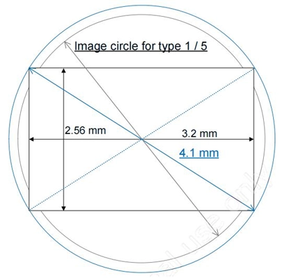
Figure 1: Relationship Between Image Circle And Pixel Area
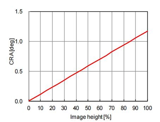
Figure 2: IMX991 CRA Characteristics
| IMX991 CRA(Chief Ray Angle)Characteristics | ||
| lmage height | CRA (deg) | |
| (%) | (mm) | |
| 0 | 0 | 0 |
| 5 | 0.1 | 0.06 |
| 10 | 0.2 | 0.12 |
| 15 | 0.31 | 0.18 |
| 20 | 0.41 | 0.23 |
| 25 | 0.51 | 0.29 |
| 30 | 0.61 | 0.35 |
| 35 | 0.72 | 0.41 |
| 40 | 0.82 | 0.47 |
| 45 | 0.92 | 0.53 |
| 50 | 1.02 | 0.59 |
| 55 | 1.13 | 0.65 |
| 60 | 1.23 | 0.7 |
| 65 | 1.33 | 0.76 |
| 70 | 1.43 | 0.82 |
| 75 | 1.54 | 0.88 |
| 80 | 1.64 | 0.94 |
| 85 | 1.74 | 1 |
| 90 | 1.84 | 1.06 |
| 95 | 1.95 | 1.12 |
| 100 | 2.05 | 1.17 |
AttosView support all Attostek UV-VISion and SWIR cameras ,it is a professional software that integrates camera control, image acquisition and processing, image browsing and analysis functions.
AttosView has the following characteristics:
ascamsdk support a variety of APIs, including: Native C/C++,.NET/C#/VB.NET, Python, Java, DirectShow, Twain, LabView, Matlab, etc. Compared with other APIs, Native C/C++ API as a low-level API is characterized by using pure C/C++ development without relying on other runtime libraries. The interface is simple and the control is flexible.
The SWIR0503 series cameras supports a variety of third-party interface software to facilitate user integration and development. Specifically, it includes SDK and demo programs for LabVIEW and MATLAB, as well as DirectShow plugins, Micro-Manager plugins, and TWAIN SDK plugins. These enable seamless compatibility with mainstream development environments and third-party software, significantly streamlining system integration and secondary development workflows.
For CameraLink interface cameras, we recommend using frame grabbers from the following brands: Magewell, FIREBIRD, and Hikvision.
Support all Attostek UV-VISion and SWIR cameras.
Click the button below to download the camera software.
LabVIEW SDK and demo programs:
MatLab SDK demo program:
DirectShow plugin:
Micromanager plugin:
TWAIN SDK plugin:
Only supports SWIR051ACL model
Magewell:
FIREBIRD:
Hikvision:
AttosView Recommended System Requirements | |
Operating System | Microsoft® Windows® XP / Vista / 7 / 8 /10 /11(32 & 64 bit), Mac OSX, Linux |
Processor (CPU) | ≥3.0 GHz Intel Core i5 or Higher |
Memory (RAM) | ≥8 GB |
Hard Drive | NVMe Solid State Drive (SSD) |
Graphics Card | Dedicated Adapter with ≥256 MB RAM |
Motherboard | USB 3.0 (-USB) Cameras: Integrated Intel USB 3.0 Controller or One Unused One Unused PCle3.0*16 Slot |
Connectivity | Internet Connectivity for Driver Installation |
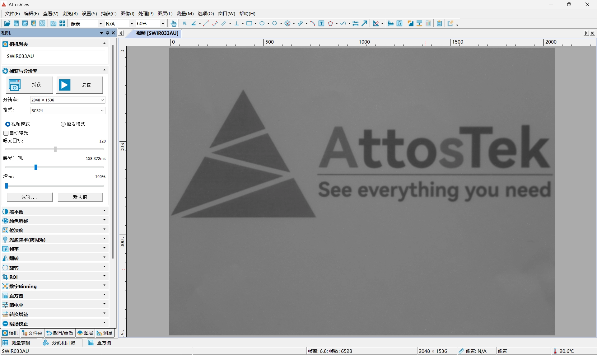
The image below shows the interface of the Attosview software. For more detailed information, please download the product manual.
Function | Function description |
Operating mode | Operating mode: video mode or trigger mode Trigger mode: soft trigger mode or external trigger mode |
Denoise | The camera hardware incorporates denoise |
Automatic exposure | Automatic exposure or manual exposure function |
| Gain | HG, MG, LG 3 gain modes |
Frame rate | Supports precise frame rate control |
ROI | Supports single-zone ROI with a maximum frame rate of 8000fps after ROI |
| Flip | Supports Vertical/horizontal flip |
| Custom dark field correction | The hardware supports up to 12 groups of user-defined dark field correction image functions |
Timestamp function | Timestamps can be turned on or off. After the timestamp function is enabled, the low 8bits of 1-8 pixels, 9-16 pixels, and 17-24 pixels will be modified to: 0-7: frame number; 8-15: Frame time; 16-23: trigger signal count |
Firmware update | Supports firmware online update |
Pipette function | Supports the display of the gray value of the mouse pixel position |
Histogram display | Supports histogram display and statistics |
| Plane line function | Supports the function of viewing surface data |
Regional gray statistics | Support the average gray statistics function of user-defined areas |
Cooling system | 1) The cooling system of the camera uses a built-in TEC cooling chip for the sensor, with external heat dissipation structure and fan auxiliary heat dissipation, the working temperature can be adjusted to a specific value, the effective cooling temperature can be lower than the ambient temperature of 40℃, and the high-efficiency cooling system ensures extremely low dark current level; 2) The TEC system adopts PID algorithm control, so that TEC can accurately adjust the sensor to the target temperature, and the temperature deviation is 0.3℃; |
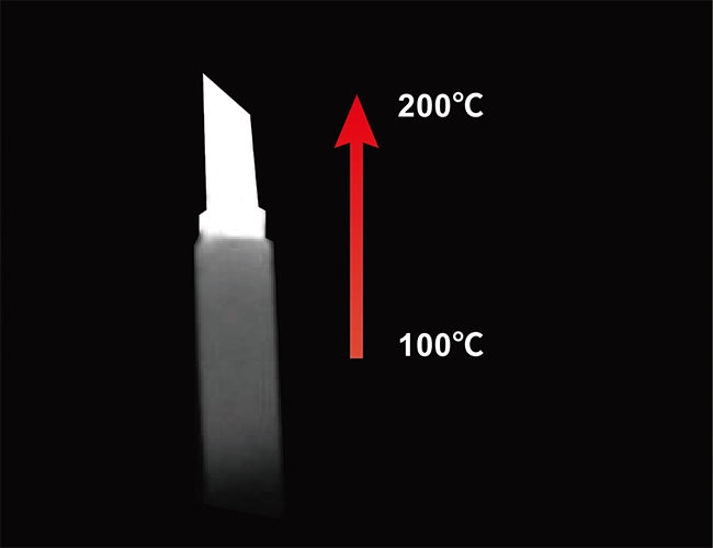
The word SWIR is an acronym meaning Short Wavelength InfraRed, also frequently referred to as shortwave infrared. SWIR generally refers to the wavelength band of light between 900nm and 2500nm. Commonly used imaging devices, such as those based on indium gallium arsenide (InGaAs) sensors, typically have a response range of 900–1700 nm. Therefore, the operational band of SWIR cameras (equipped with InGaAs sensors) is usually 900–1700 nm.
Not exactly. Traditional night vision often amplifies visible and near-infrared light. SWIR imaging uses a different part of the spectrum and can provide clearer images in certain low-light scenarios and through atmospheric obscurants where traditional night vision might struggle.
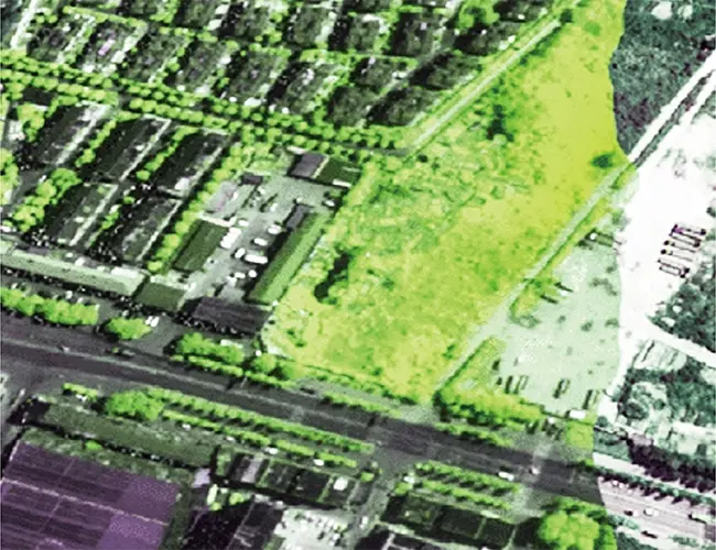
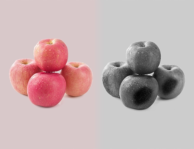
Objects that appear as nearly identical colors or shades to a visible-light camera can be easily distinguished and made recognizable when imaging with SWIR light.
Semiconductor Industry: Inspection of solar cells and semiconductor chips.
Plastics Sorting: Different plastics have different reflectance spectra in the SWIR band, enabling accurate classification and recycling of black plastics.
Glass Industry: Defect detection through hot glass.
Security: Counterfeit detection, such as in currency, wigs, or skin.
| Model | SWIR0503AU | SWIR0503AG | SWIR0503ACXP | SWIR0503ACL |
| Sensor Type | Sony IMX991 InGaAs | |||
| Spectral Range | 400nm-1700nm | |||
| Pixel Size | 5.0 µm x 5.0 µm | |||
| FPS/Resolution | 8bit: 400fps@640 x 512、 753fps@320 x 256 12bit: 212fps@640 x 512、 400fps@320 x 256 | 8bit: 257.8fps@640 x 512、 486.1fps@320 x 256 12bit: 137.1fps@640 x 512、 258.6fps@320 x 256 | 8 Bit:258fps@656×520、486fps@328×260 10 Bit:240fps@656×520、451fps@328×260 12 Bit:137fps@656×520、258fps@328×260 | 8 Bit:350fps@640 x 512、 657fps@320 x 256 12bit:188fps@640 x 512、 350fps@320 x 256 |
| Data interface | USB3.0 | GigE | CoaxPress | CameraLink |
| Binning Mode | Software2x2, 3×3, 4×4 | Not supported | ||
| Size | 80mm×80mm×45.5mm | 75mm×75mm×81.9mm | ||
| Software | AttosView / SDK | SDK /CLView | ||
To meet the diverse application demands of short-wave infrared (SWIR) imaging, Attostek offer a series of high-performance SWIR lenses. This lineup covers focal lengths from 6mm to 100mm and features a wide aperture range of F1.4 to F2.0 as standard, ensuring high signal-to-noise ratio and superior image quality even in low-light conditions. Users can flexibly select different models based on field of view, working distance, and resolution requirements, providing high sensitivity and versatile scene adaptability for SWIR cameras in applications such as security surveillance, industrial inspection, and scientific research.