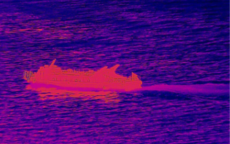
0.33MP 15μm Pixels, 3.7–4.8μm MCT MWIR Camera Core
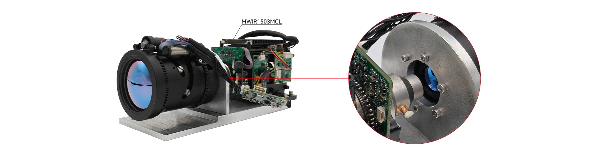
| Features |
| 3.7 – 4.8 µm spectral range |
| 640 × 512 resolution |
| 15 μm × 15 μm pixel size |
| Linear Stirling Cryocooler |
| With RS422/RS232 interface |
| Digital output is provided via Camera Link |
| Detector Type | MCT |
| Resolution | 640×512 |
| F-Number | 4.0 |
| Pixel Size | 15 μm×15 μm |
| Response Band | 3.7 μm~4.8 μm |
| Cold Shield Distance | 20.0±0.2mm |
| Cooling Method | Linear Stirling Cryocooler |
| Cool-Down Time | ≤8min@20℃,≤12min@60℃ |
| Mean Time To Failure (MTTF) | ≥15000h (lifespan of cooler-related components) |
| NETD | ≤20 mk |
| Dead Pixels | ≤0.5% |
| Frame frequency | Default 50Hz, user-selectable range |
| Electrical Interfaces | Camera Link video; RS422/RS232 communication; BT656 power supply |
| Stable Power Consumption | ≤ 16W @ 20°C |
| Peak Power Consumption | ≤ 24W @ 20°C |
| Maximum Power Consumption | ≤ 32W |
| Power Supply | DC 12-32V |
| Video Output | PAL (resolution 720×576, effective 640×512) BT656 (progressive or interlaced, default interlaced) Camera Link (14-bit Base mode) |
| Expandable Video | Network, SDI |
| Common Functions | Auto/Manual AGC, Two-point Correction, Shutter Correction, Scene Correction, Zoom, Image Freeze, Polarity & False Color, DDE, Defect Correction, External Sync, Image Flip |
| Operating Temperature | -40°C ~ +70°C |
| Storage Temperature | -50℃~+70℃ |
| Vibration (Random Vibration) | 5Hz ~ 28Hz, 0.0036 g²/Hz ~ 0.08 g²/Hz 28Hz ~ 250Hz, 0.08 g²/Hz 250Hz ~ 2000Hz, 0.08 g²/Hz ~ 0.0012 g²/Hz 3 axes (x, y, z), 1 hour per axis |
| Shock | Half-sine, 50g, 6ms (3 axes, 3 shocks per axis) Half-sine, 40g, 18ms (3 axes, 3 shocks per axis) Half-sine, 25g, 6ms (3 axes, 3 shocks per axis) |
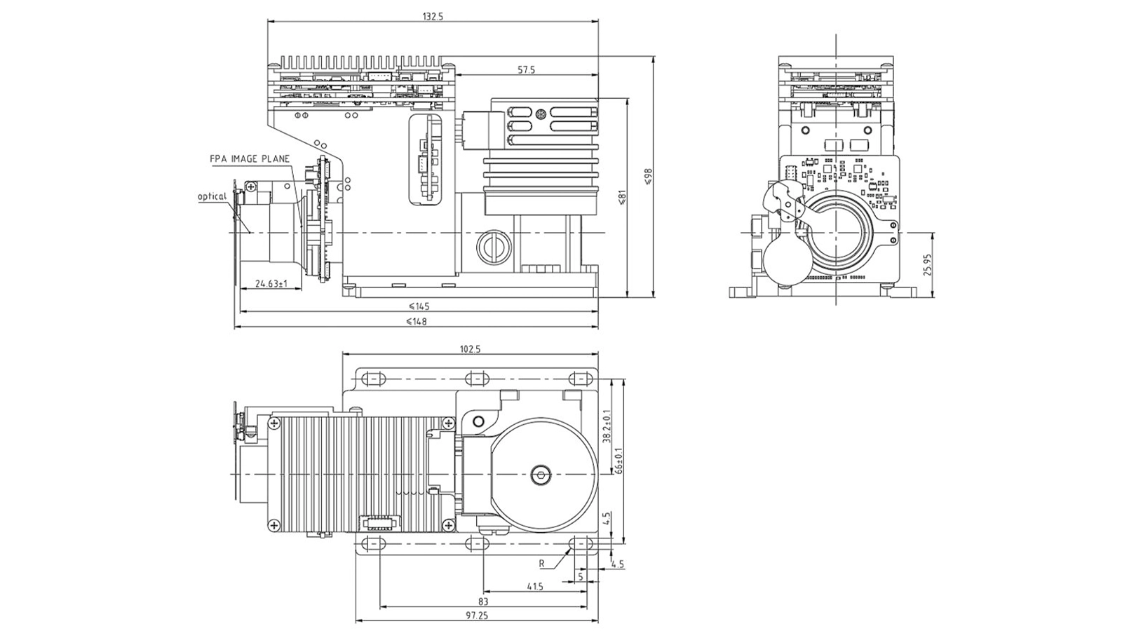
| Dimensions | L148mm×W75mm×H98mm |
| Weight | ≤1150g |
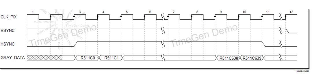
Parameter row Correspondence Table
| Pixels | Data (bit15-0) | Notes |
| pix0 | 55AA | Frame header |
| pix1 | AA55 | |
| pix2 | AAAA | |
| pix3 | 5555 | |
| pix4 | Low position | Frame number |
| pix5 | High position | |
| pix6 | DATA | Synchronous mode (Bit8:0 inside, 1 outside) + system mode (bit1-0) |
| pix7 | DATA | Current base range (Bit15-12) + total temperature range (Bit11-8) + current integral range (Bit7-4) + total integral range (Bit3-0) |
| pix8 | Low position | Integral clock count |
| pix9 | High position | |
| pix10 | DATA | Focal length |
| pix11 | DATA | Detector power-on status (bit0:0: power-off, 1 power-on) |
| pix12 | DATA | This cooling completion time unit: s |
| pix13 | DATA | Ambient temperature, magnified 10 times, signed number |
| pix14 | DATA | Focal plane temperature, magnification 10 |
| pix15 | DATA | Polarity/pseudo-color (bit2-0) |
| pix16 | DATA | Digital video mode (BIT1-0, 0: Y14, 1: Y8, 2: X14) |
| pix17 | DATA | Frame rate, magnify 100 times |
| pix18 | DATA | Electronic doubling (bit1-0) |
| pix19 | DATA | Sharpening level (bit3-0) |
| pix20 | DATA | Mirror mode (bit1-0) |
| pix21 | DATA | Time-domain filtering mode (bit0, 0: off, 1: on) |
| pix22 | DATA | Time-domain filtering parameters |
| pix23 | DATA | Airspace filter switch (bit0, 0: off, 1: on) |
| pix24 | DATA | Spatial filtering threshold |
| pix25 | DATA | Brightness (Bit 7-0) |
| pix26 | DATA | Contrast (bit7-0) |
| Pixels | Data (bit15-0) | Notes |
| pix0 | 55AA | Frame header |
| pix1 | AA55 | |
| pix2 | AAAA | |
| pix3 | 5555 | |
| pix4 | Low position | Frame number |
| pix5 | High position | |
| pix6 | DATA | Synchronous mode (Bit8:0 inside, 1 outside) + system mode (bit1-0) |
| pix7 | DATA | Current base range (Bit15-12) + total temperature range (Bit11-8) + current integral range (Bit7-4) + total integral range (Bit3-0) |
| pix8 | Low position | Integral clock count |
| pix9 | High position | |
| pix10 | DATA | Focal length |
| pix11 | DATA | Detector power-on status (bit0:0: power-off, 1 power-on) |
| pix12 | DATA | This cooling completion time unit: s |
| pix13 | DATA | Ambient temperature, magnified 10 times, signed number |
| pix14 | DATA | Focal plane temperature, magnification 10 |
| pix15 | DATA | Polarity/pseudo-color (bit2-0) |
| pix16 | DATA | Digital video mode (BIT1-0, 0: Y14, 1: Y8, 2: X14) |
| pix17 | DATA | Frame rate, magnify 100 times |
| pix18 | DATA | Electronic doubling (bit1-0) |
| pix19 | DATA | Sharpening level (bit3-0) |
| pix20 | DATA | Mirror mode (bit1-0) |
| pix21 | DATA | Time-domain filtering mode (bit0, 0: off, 1: on) |
| pix22 | DATA | Time-domain filtering parameters |
| pix23 | DATA | Airspace filter switch (bit0, 0: off, 1: on) |
| pix24 | DATA | Spatial filtering threshold |
| pix25 | DATA | Brightness (Bit 7-0) |
| pix26 | DATA | Contrast (bit7-0) |
The core’s external interfaces include: power interface, RS422 external control interface, analog video interface, digital video CameraLink interface, BT656 interface, and control lens interface. The first four physical interfaces are connected via a 25-pin connector, while the BT656 interface is connected via a 20-pin 0.5mm pitch FPC connector (pull-down type). The model of the 25-pin connector on the circuit board is J30JZLN25ZKWA000, and the corresponding mating connector’s model and definitions are shown in Table 1. The FPC connector pin definitions are shown in Table 2.
| Pin Number | Name | Definition |
| 1,2 | POWER+ | Power Positive |
| 14,15 | POWER- | Power Ground |
| 3 | RS422_A1 | Core Receive + |
| 4 | RS422_B1 | Core Receive – |
| 5 | RS422_Y1 | Core Transmit + |
| 6 | RS422_Z1 | Core Transmit – |
| 7 | GND | RS422 Serial Port Ground |
| 8 | RS422_A2 | External Sync Receive + |
| 9 | RS422_B2 | External Sync Receive – |
| 10 | PAL_OUT1 | Analog Video |
| 11 | AGND_ADV7179 | Analog Video Ground |
| 12 | PAL_OUT2 | Backup Analog Video |
| 13 | AGND_ADV7179 | Backup Analog Video Ground |
| 16 | Tx285OUT0+ | Digital Video |
| 17 | Tx285OUT0- | |
| 18 | Tx285OUT1+ | |
| 19 | Tx285OUT1- | |
| 20 | Tx285OUT2+ | |
| 21 | Tx285OUT2- | |
| 22 | Tx285OUT3+ | |
| 23 | Tx285OUT3- | |
| 24 | Tx285CLK+ | |
| 25 | Tx285CLK- |
| Pin Number | Name | Definition |
| 20 | BT656_CLK | Clock |
| 19 | BT656_D0 | Data Bit 0 |
| 18 | BT656_D1 | Data Bit 1 |
| 17 | BT656_D2 | Data Bit 2 |
| 16 | BT656_D3 | Data Bit 3 |
| 15 | BT656_D4 | Data Bit 4 |
| 14 | BT656_D5 | Data Bit 5 |
| 13 | BT656_D6 | Data Bit 6 |
| 12 | BT656_D7 | Data Bit 7 |
| 11/10/9 | DGND | Ground |
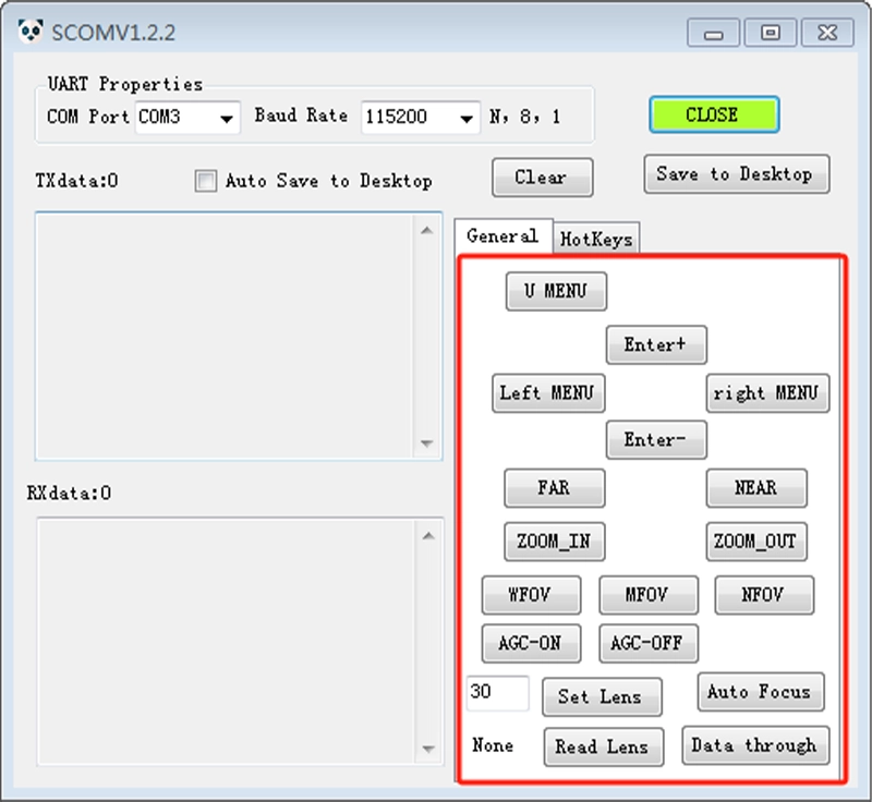
The control serial port of the upper computer for the infrared movement is “SSCOM_INF_EN English new version.exe” (referred to as the control serial port). Double-clicking the file will generate the control interface.
The software operation steps are:
1) : Correctly select the port number of the serial port (depending on the computer being used), set the baud rate (115200 BPS), and then click “Open Serial Port”. After the correct Settings, the control serial port interface changes to the one shown in the figure on the right. The green box in the figure turns green, indicating that the control serial port is working properly.
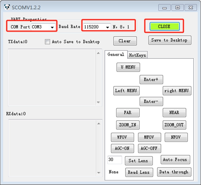
2) Introduction to the control serial interface, with the red box representing quick commands, users can control the MWIR1503MCL infrared movement by clicking the buttons inside the box.
| Quick Commands | Meanings | Quick Commands | Meanings |
| Menu | User menu, with only a few control functions | Expert Menu | Unavailable |
| Parameter + | Forward adjustment of parameters in the image | Parameter | Reverse adjustment of parameters in the image |
| Menu left shift | Move the parameters in the image left and right | Move the menu right | Move the parameters in the image left and right |
| FAR | Focus close | NEAR | Focus far |
| ZOOM_IN | Zoom in length | ZOOM_OUT | Push out the focal length |
| Serial pass-through | Click this command to release the serial communication to the lens serial port | Set the focal length | The focal length can be set manually |
| Focal length Query | Query lens focal length |
Q1:What are the advantages of mid-wave infrared (MWIR) compared to long-wave infrared (LWIR)?
Under the same conditions, MWIR can detect targets at about 2.5 times the distance of LWIR;
It is less sensitive to the atmospheric environment and performs well in good weather;
It is highly sensitive to temperature differences of high-temperature targets (like engine exhaust or hot components), has strong thermal contrast, and is suitable for detecting targets in dynamic scenes.Q2:What is an MCT detector? Why do mid-wave infrared detectors have to use a cooled module?
MCT stands for Mercury Cadmium Telluride, which is a photon-type infrared detection material. It’s optimized for the 3.7–4.8 μm mid-wave infrared range, offering excellent sensitivity and response speed, making it suitable for high-performance thermal imaging. Mid-wave infrared photons have relatively high energy, so a Stirling cooler is needed to bring the focal plane down to a low temperature, reducing the detector’s own thermal noise. This allows for high-sensitivity imaging of ≤20 mK. Uncooled vanadium oxide detectors can’t work in the mid-wave infrared range.
Q3:What does cooling time mean, and how should we understand a refrigeration unit lifespan of ≥15,000 hours?
Cooling time: ≤8 minutes in a 20°C environment, ≤12 minutes in a 60°C high-temperature environment. This represents the time it takes from startup for the detector to reach its rated operating low temperature. The ≥15,000 hours refers to the designed service life of the refrigeration components, not the unconditional lifespan of the entire machine; vibrations, high temperatures, and frequent start-stop cycles can shorten the actual service life of the unit.
640 X 512 MWIR Cooled MCT Infrared Camera Core
MWIR1503MCL
MWIR Thermal Cameras Core with MCT Detector, 15 µm Pixel
Optional accessories – MWIR Lenses
Our Mid-Wave Infrared (MWIR) lens offers a wide range of optical solutions to enhance your thermal imaging system. They are designed to meet a wide range of detection, recognition, and identification requirements . Available as optional accessories, the lineup includes continuous zoom lenses covering ranges from 15‑300mm up to 60‑1200mm with aperture options of f/4.0 or f/5.5 depending on the model.
MW275S
18–275mm EFL, F/5.5 MWIR Motorized Zoom Lens, for 640×512 (15μm) Detector
MW300S
15-300mm EFL, F/4 MWIR Motorized Zoom Lens, for 640×512 (15μm) Detector
MW360S
40-360mm EFL, F/4 MWIR Motorized Zoom Lens, for 640×512 (15μm) Detector
MW550S
30-550mm EFL, F/5.5 MWIR Motorized Zoom Lens, for 640×512 (15μm) Detector
MW600S
30-600mm EFL, F/4 MWIR Motorized Zoom Lens, for 640×512 (15μm) Detector
MW900S
45-900mm EFL, F/4 MWIR Motorized Zoom Lens, for 640×512 (15μm) Detector
MW1200S
80-1200mm EFL, F/4 MWIR Motorized Zoom Lens, for 640×512 (15μm) Detector