C-Mount UV Fixed Focal Lens
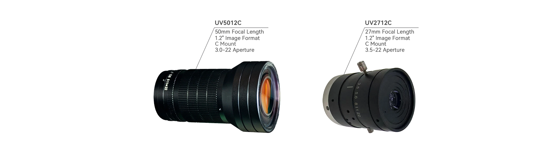
| No. | Item | UV2712C | UV5012C |
| 1 | Image Format | 1.2″ | |
| 2 | Image Circle | Ø21.0 mm(Max) | |
| 3 | Optical EFL | 27 mm | 50 mm |
| 4 | Aperture | 3.5–22 | 3.0–22 |
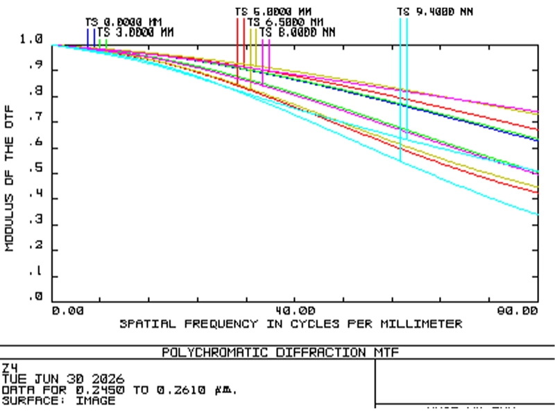
| 5 | Resolution | 10 MP | |
| 6 | System TTL | 67.5 ± 1.0 mm | 118.29 ± 2.0 mm |
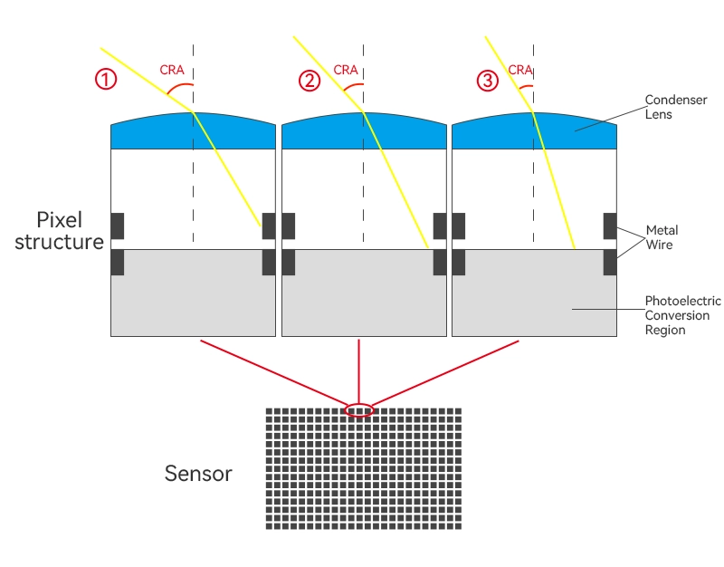
| 7 | Chief Ray Angle(CRA) | <16.5°(Max) | <10° |
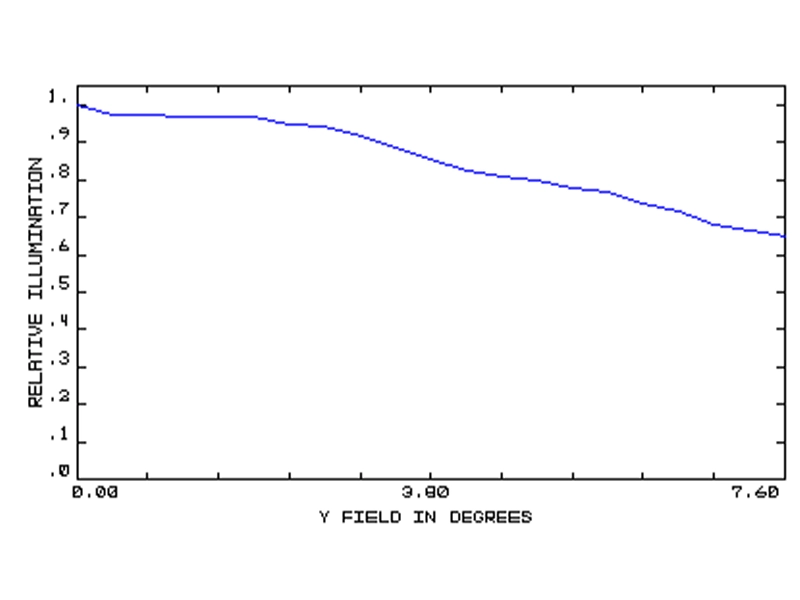
| 8 | Illumination | >60% (Min) | |
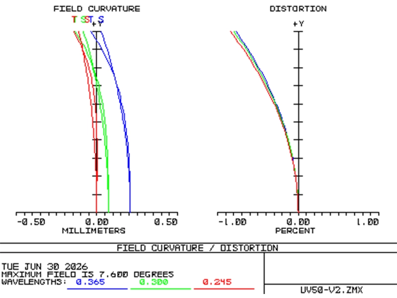
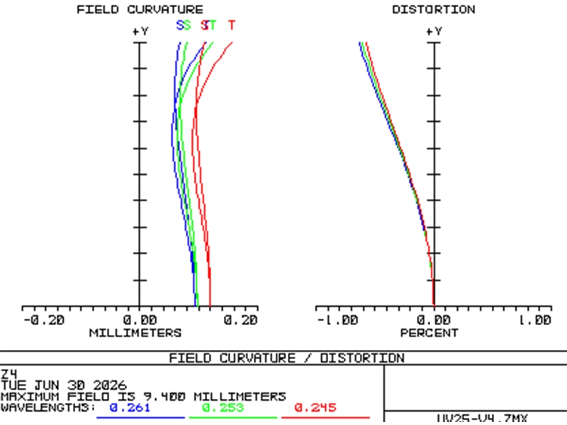
| 9 | Distortion | <-1.8%(Max) | <-1.0% |
| 10 | Optical BFL | / | |
| 11 | Mechanical BFL | 17.50 mm | / |
| 12 | Dimension | Ø40.50×50.0 mm | Ø60.50×100.79 mm |
| 13 | Mount | C-Mount | |
| 14 | IR Correction | / | |
| 15 | Element | / | |
| 16 | Wavelength | 200–900 nm | 200–1100 nm |
| 17 | Working Distance | 0.15 m – ∞ | |
| 18 | Temperature | -20 ℃ ~ +60 ℃ | |
| 19 | Zoom Operation | Fixed | |
| 20 | Iris Operation | Manual | |
| 21 | Focus Operation | Manual | |
| Model | Sensor Specification | Working Distance (WD) | Field of View |
| UV2712C | 2048×2048 6.5μm 13.3×13.3mm |
WD=3.0m | 36.0°×25.7°×25.7° |
| WD=1.2m | 35.7°×25.5°×25.5° | ||
| WD=0.15m | 32.5°×23.4°×23.4° | ||
| UV5012C | WD=2.0m | 20.7°×4.6°×14.6° | |
| WD=0.25m | 17.4°×13.3°×13.3° | ||
| WD=0.15m | 15.1°×10.6°×10.6° |
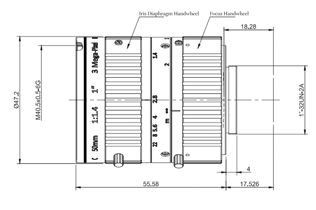
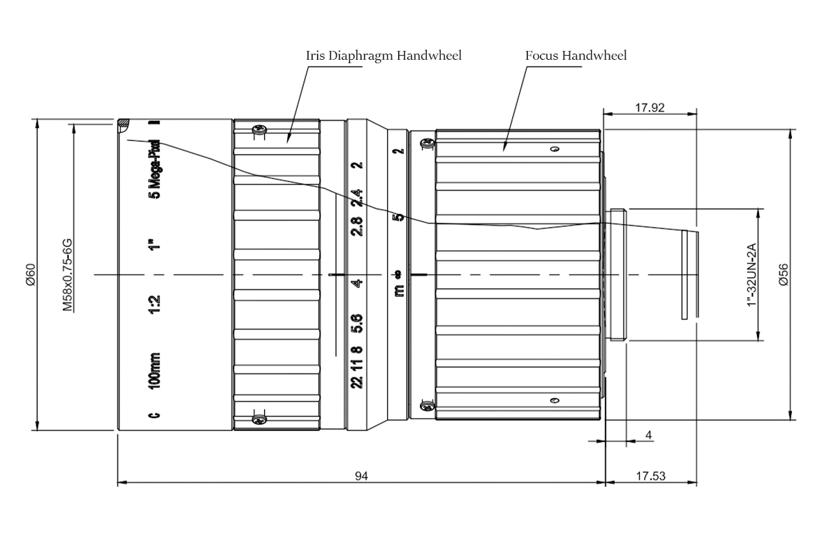
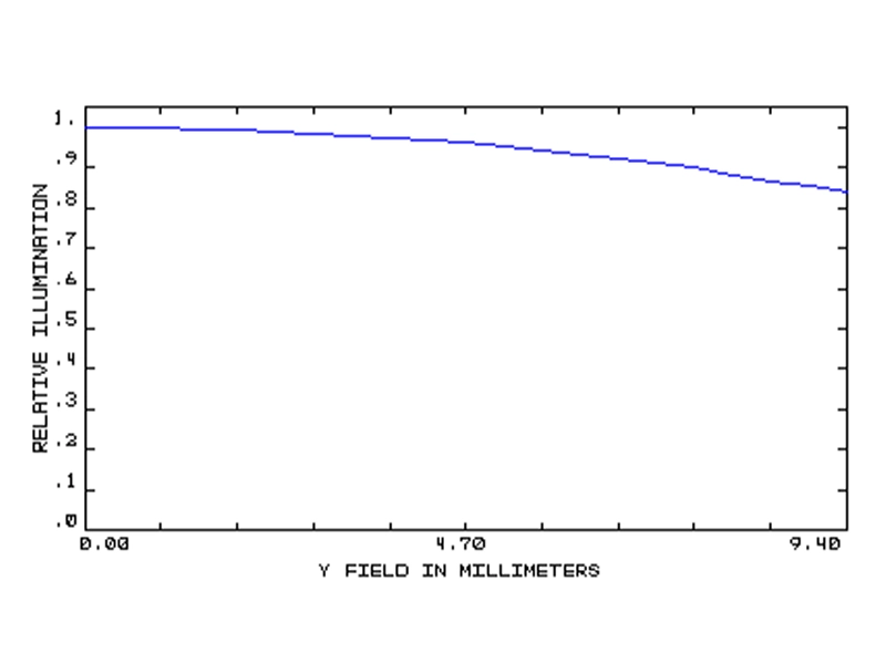
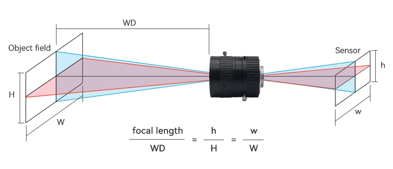
Focal length refers to the distance between the optical center (rear principal point) of a lens and its imaging focal point, serving as a key performance parameter of the lens. It determines the angle of view: the shorter the focal length, the wider the field of view and the broader the observable range; the longer the focal length, the narrower the field of view and the more concentrated the observation area.
The aperture controls the amount of light entering the lens—a larger aperture results in a brighter image. This parameter directly affects exposure time and, consequently, the camera’s response speed. In daytime shooting, if the light is too strong, the aperture can be narrowed to prevent overexposure; at night or in low‑light conditions, the aperture can be widened to increase light intake, ensuring optimal imaging performance under varying lighting conditions.
The optical lens interface refers to the standardized mechanical mount connecting a lens to a camera body, determining compatibility and ensuring precise alignment for correct optical focus onto the image sensor. In industrial applications, C-mount and CS-mount are generally employed with cameras featuring smaller sensor sizes, while F-mount is typically used for larger sensors. Additional interfaces commonly found in line-scan cameras include M42, M58, and M72 mounts—essentially threaded connections of specified diameters.
C-mount lenses represent the established standard in machine vision, compatible with cameras housing image sensors up to approximately 20 mm (1.5 inches) in diagonal dimension. This interface supports a wide array of specifications across focal lengths, resolutions, and working distances. All SWIR fixed lenses provided by Attostek are designed with C-mount connectivity.
When used with a larger sensor, the edges of the sensor extend beyond the lens’s image circle, resulting in dark corners or black borders around the photo.
To ensure optimal imaging performance, it is generally required that the lens CRA should match the sensor CRA, with the lens CRA not exceeding that of the sensor.
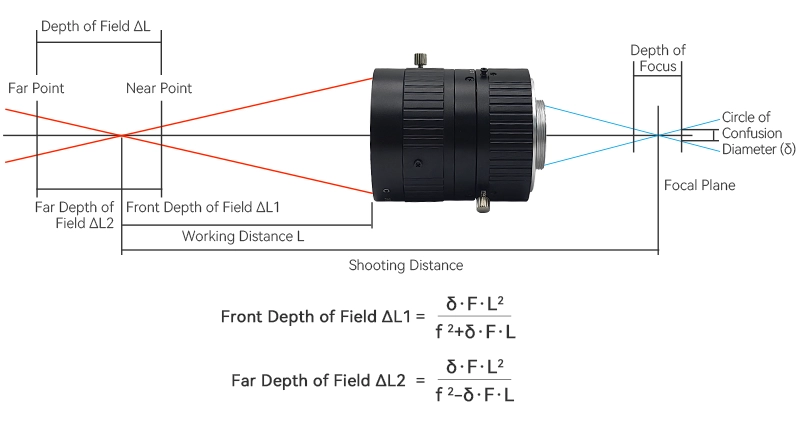
Three primary factors influence depth of field: aperture size, working distance, and lens focal length. Increasing the depth of field can be achieved by:
- Reducing the aperture size (i.e., using a larger f-number)
- Increasing the working distance
- Using a lens with a shorter focal length
Q1:How to choose between the UV2712C and UV5012C?
The UV2712C lens has a 200-900nm spectral range, CRA <16.5°, and a wider field of view, making it suitable for ultraviolet defect detection and fluorescence imaging that require a broad view.
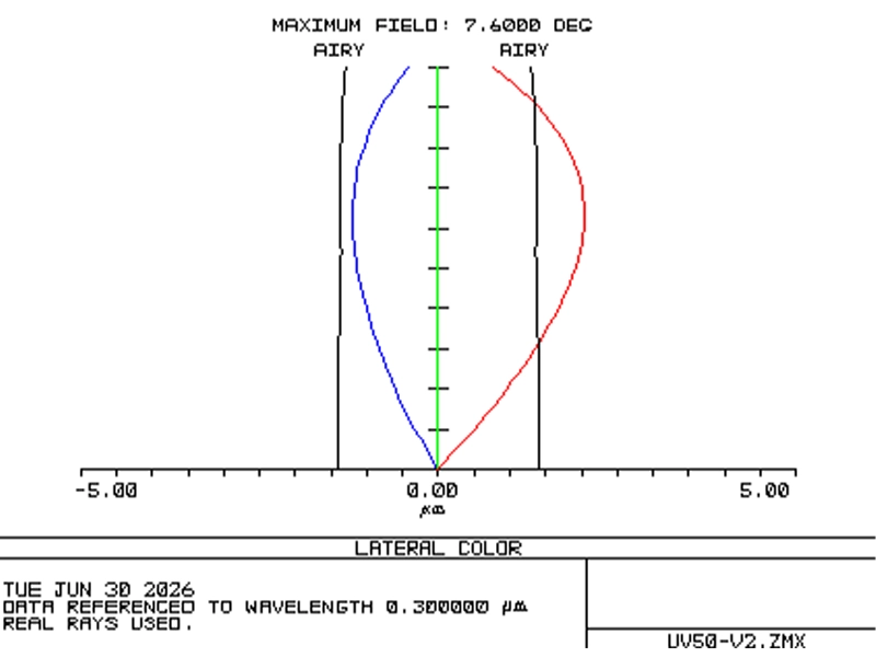
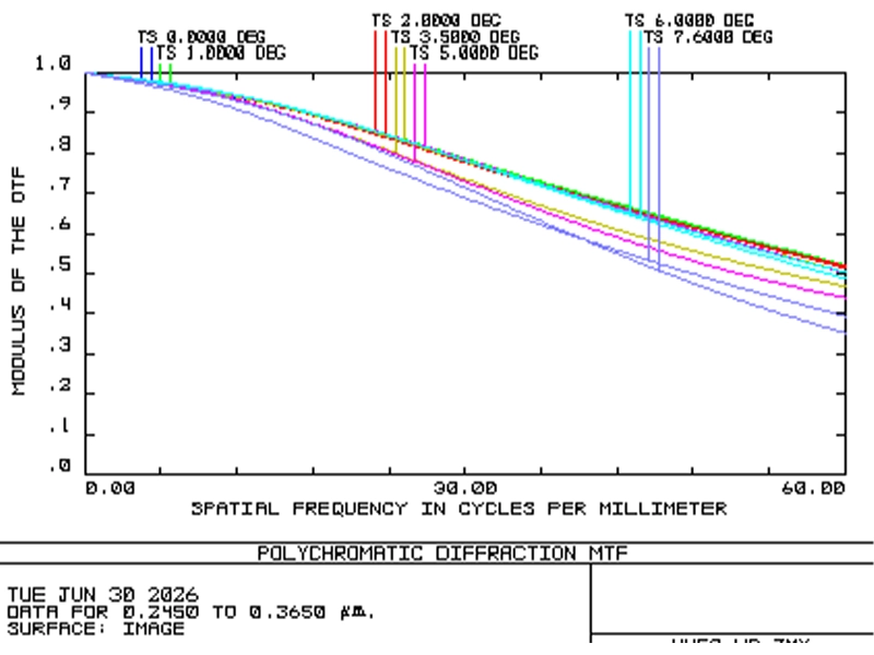
The UV5012C covers a 200-1100nm spectral range, so it captures a wider spectrum. With CRA <10°, it has a narrower field of view, focusing on a concentrated observation area. It also has less imaging distortion, making it ideal for material analysis, biological observation, and high-precision visual inspections.
Q2:What does a minimum working distance of 0.15m mean, and can it be used below 0.15m?
0.15m is the minimum focusing distance designed for this lens. If an object is closer than 0.15m, the lens won’t be able to focus properly, and the image will stay blurry. It’s not recommended to use it for scenes closer than 0.15m.
Q3:Can a regular visible light industrial lens be used to replace this UV lens for UV imaging?
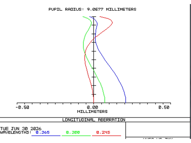
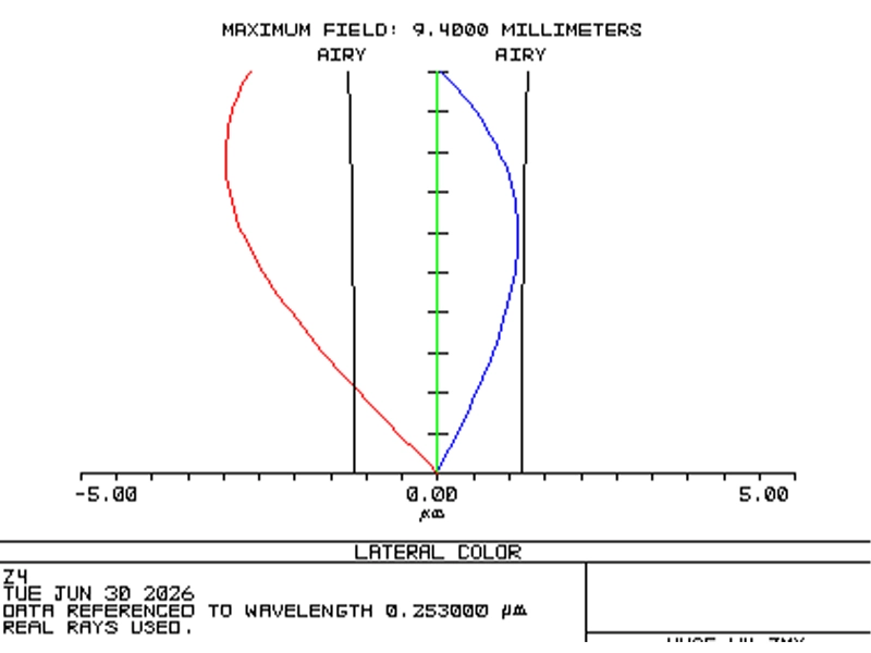
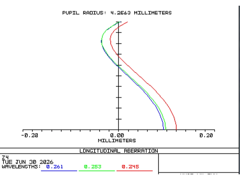
Not recommended. Regular visible light lenses are optimized for the 400–700nm visible light range with their optical glass and anti-reflective coatings. They have low transmission, severe chromatic aberration, focal shift, and greatly reduced resolution in the 200–400nm UV range. Our UV lenses, on the other hand, have optical elements and coatings optimized for a wide UV-visible spectrum, ensuring good transmission and image quality starting from 200nm.
27mm / 50mm Fixed Focal Lenses for C-Mount UV Cameras
Attostek UV2712C and UV5012C are 1.2″ 10MP UV fixed lenses available in 27mm and 50mm focal lengths with standard C-mount. The UV2712C covers a spectral range of 200–900 nm, while the UV5012C covers 200–1100 nm. Both lenses feature manual iris and manual focus mechanisms to adapt flexibly to different working distances and lighting conditions. They are widely used in UV defect inspection, fluorescence imaging, material analysis, biological observation, precision visual inspection and other applications.