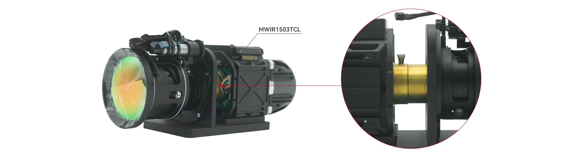
0.33MP 15μm Pixels, 3.7–4.8μm T2SL MWIR Camera Core
| Features |
| 3.7µm – 4.8µm spectral response |
| 640 × 512 resolution with 15 μm × 15 μm pixel size |
| High frame frequency and high sensitivity |
| Linear stirling cryocooler |
| Digital output is provided via Camera Link |
| Supporting 14-bit raw data or 8-bit video data |
| Detector Type | Type-II Superlattice Mid-Wave Infrared Detector |
| Resolution | 640×512 |
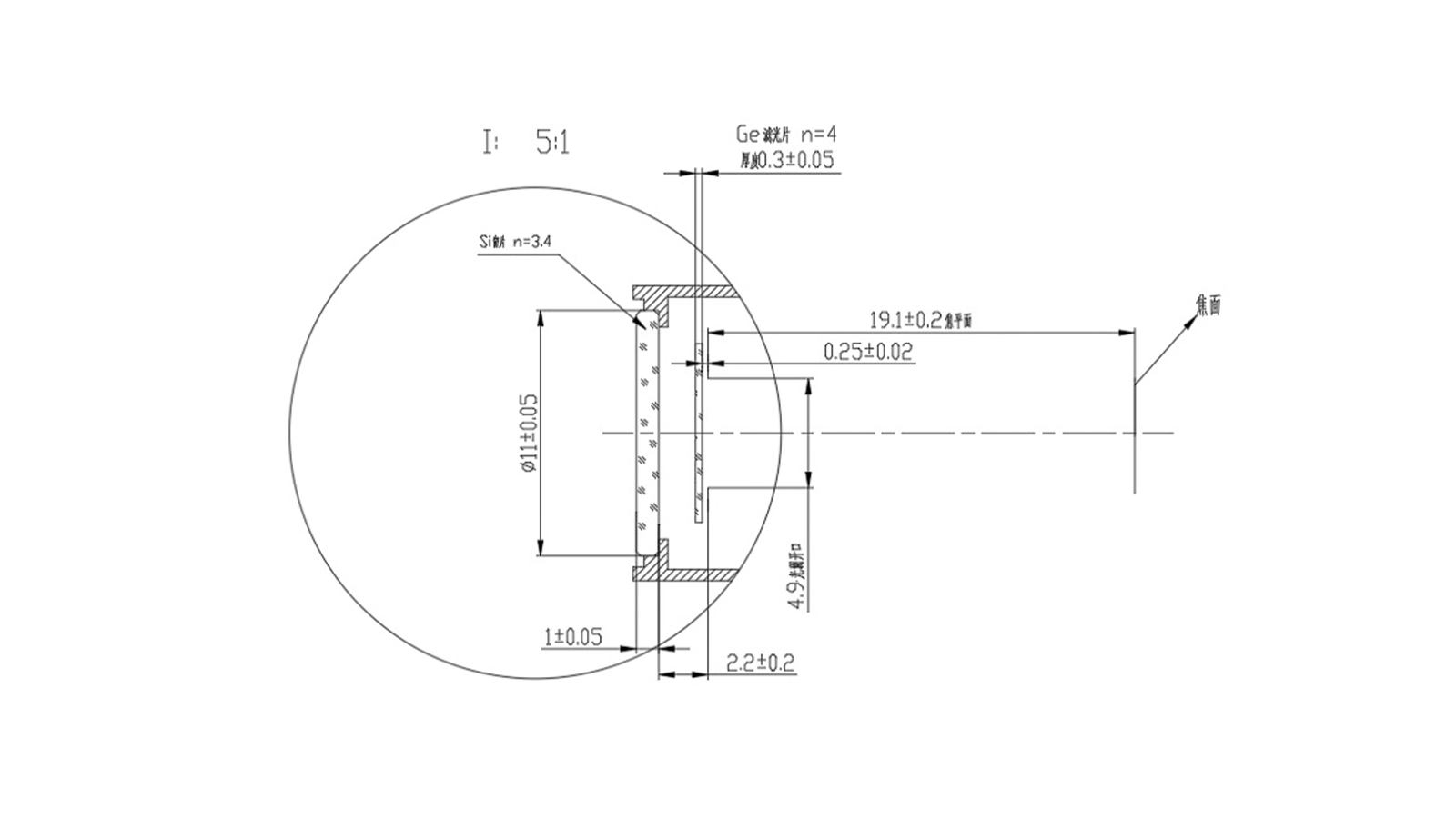
| F-Number | 4 |
| Pixel Size | 15 μm×15 μm |
| Response Band | 3.7 μm~4.8 μm |
| Bad Pixel Ratio | <0.3% |
| Full-Temperature Cooling Time | <7 mins |
| Cooling Method | Linear Stirling Cryocooler |
| Mean Time To Failure (MTTF) | 10000 h |
| NETD | ≤22 mk |
| Frame frequency | 25Hz/50Hz/100Hz/External Sync |
| Analog Output | PAL/NTSC System |
| Digital Output | Camera-link (14-bit raw data or 8-bit video data) |
| Image Adjustment | Contrast, Brightness, Image Polarity, Shutter Correction, Background Correction, Detail Enhancement, Electronic Zoom |
| Crosshair Reticle | Show/Hide |
| Integration Time | Continuously adjustable (6ms~20ms) |
| Input Voltage | DC12±1V |
| Cooling Power Consumption | < 28W (Peak current 3.5A in full temperature range) |
| Stable Power Consumption | < 12W |
| Operating Temperature | -40℃~+60℃ |
| Storage Temperature | -50℃~+70℃ |
| Vibration (Random Vibration) | 10Hz~80Hz, 0.01g²/Hz 80Hz~350Hz, 0.02g²/Hz 350Hz~500Hz, 0.02g²/Hz~0.01g²/Hz (Linear decrease) 3 axes (X, Y, Z), 40min/axis |
| Shock | Post sawtooth wave, 30g/11ms, shock test performed on 3 mutually perpendicular axes (X, Y, Z), 3 times forward and reverse per direction, total 18 times. |
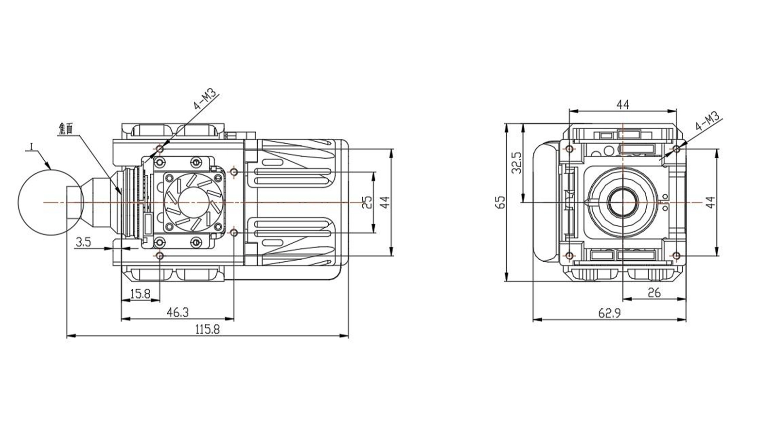
| Dimensions | 116mm×63mm×65mm |
| Weight | ≤420g |
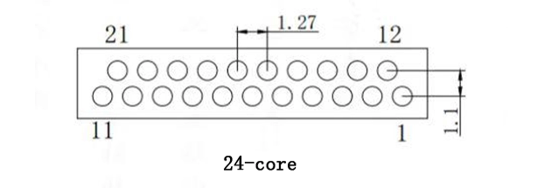
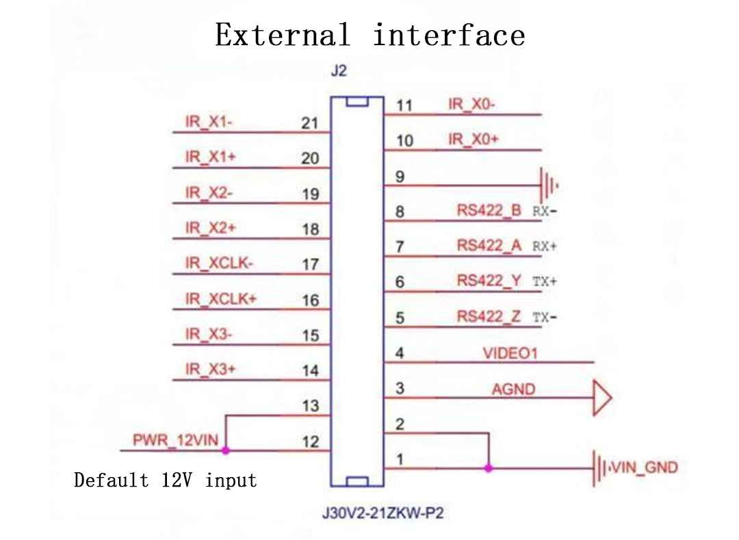
| Pin No. | Definition | Description |
| 12, 13 | VIN+ | Positive Power Input (+12V) |
| 1, 2 | VIN- | Negative Power Input |
| 3 | AGND | Analog Video |
| 4 | VIDEO1 | |
| 5 | RS422_Z TX- | RS422 Serial Port |
| 6 | RS422_Y TX+ | |
| 7 | RS422_A RX+ | |
| 8 | RS422_B RX- | |
| 9 | GND | camera-link |
| 10 | IR_X0+ | |
| 11 | IR_X0- | |
| 14 | IR_X3+ | |
| 15 | IR_X3- | |
| 16 | IR_XClk+ | |
| 17 | IR_XClk- | |
| 18 | IR_X2+ | |
| 19 | IR_X2- | |
| 20 | IR_X1+ | |
| 21 | IR_X1- |

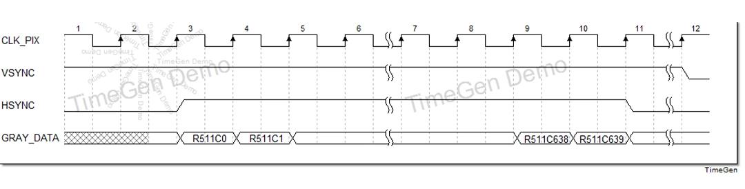
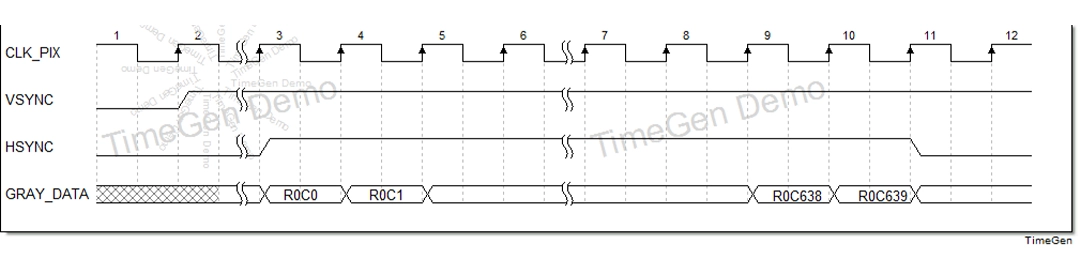
GENE Parallel Digital Video Output Interface Timing
Users can operate via the host computer software by connecting through an RS422 serial port cable, with the following defined content.
|
Item |
Value |
|
Baud Rate |
115200 bps |
|
Data Bits |
8 bit |
|
Stop Bits |
1 bit |
|
Parity |
None |
Ensure the correct software is used and click to open.
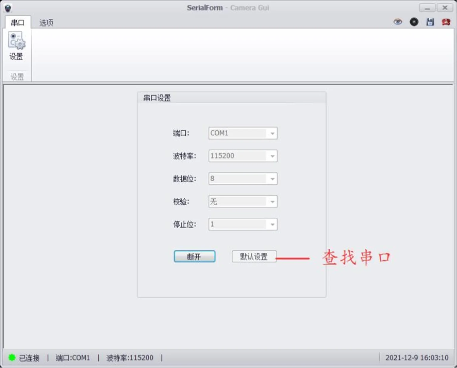
Select the Serial Port (UART) option and enter the Settings interface.
Select the correct COM port number, set the baud rate to 115200, and click Connect. A prompt box will pop up to indicate a successful connection.
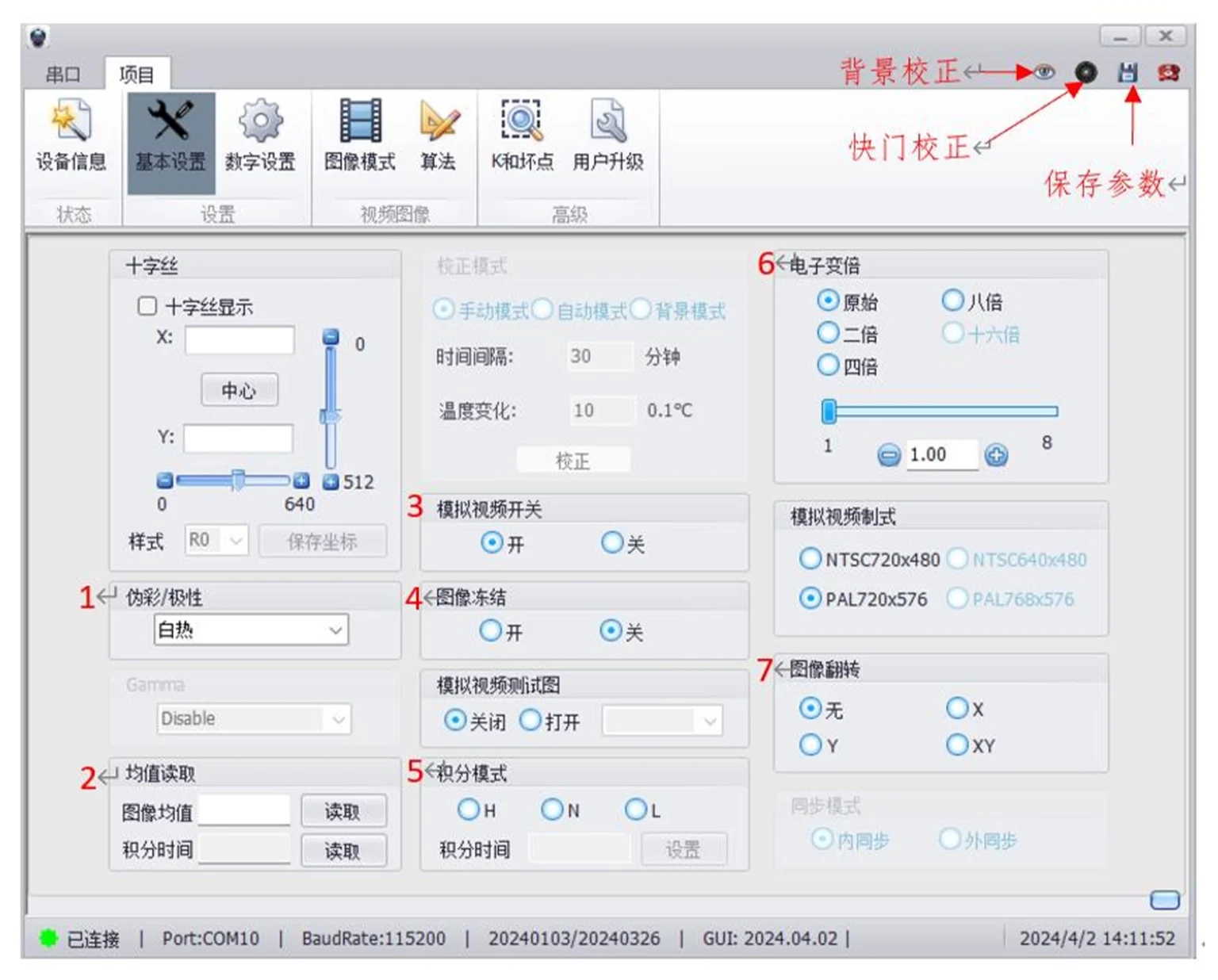
-
- Polarity Setting:
Select either Black Hot or White Hot image polarity mode. - Read Image Mean Value.
- Analog Output Switch:
Controls the analog image output. - Image Freeze:
Controls the image freeze function. - Set Integration Time:
Select different integration times based on different temperature ranges (H: High; N: Normal; L: Low). - Zoom:
Select the corresponding magnification factor to achieve center magnification. - Mirror Flip Control:
After vertical image flip, correction is required. - Shortcut Function Keys:
· Background Correction;
· Shutter Correction;
· Save User Parameters;
· Disconnect Serial Port.
- Polarity Setting:
Note: When starting up to display an image or adjusting the integration time, a uniformly surfaced object (e.g., A4 paper) must be used to cover the lens portion for background correction.
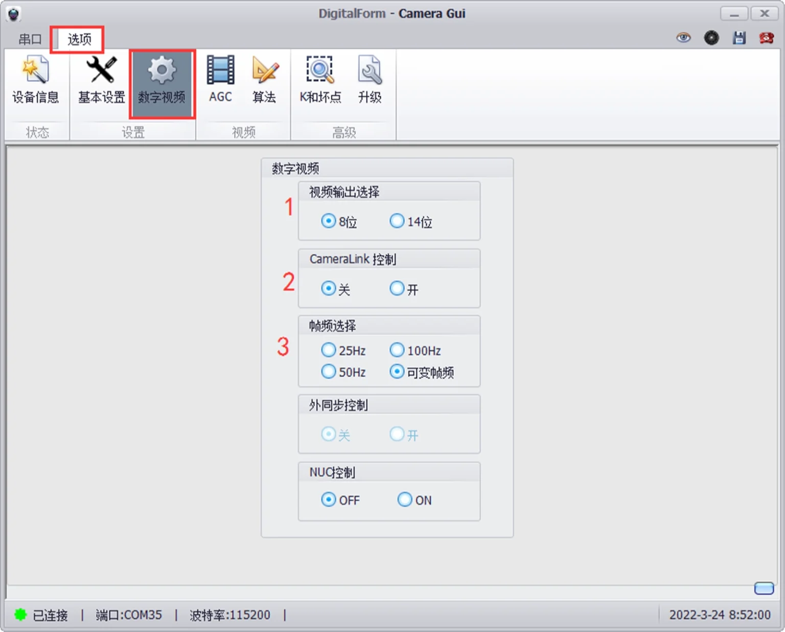
- Camera-link Output Selection:
8-bit: Outputs 8-bit video data after AGC;
14-bit: Outputs data after non-uniformity correction. - Camera-link Control Enable:
OFF: Disables camera-link output;
ON: Enables camera-link output. - Frame Rate Selection:
Select output frame rate: 25Hz, 50Hz, 100Hz.
When using a gas detector, the default mode is Variable Frame Rate, where the frame rate varies with the integration time
1. If background correction is not performed, the background may be incorporated into the image during startup or integration time changes; background correction is required.
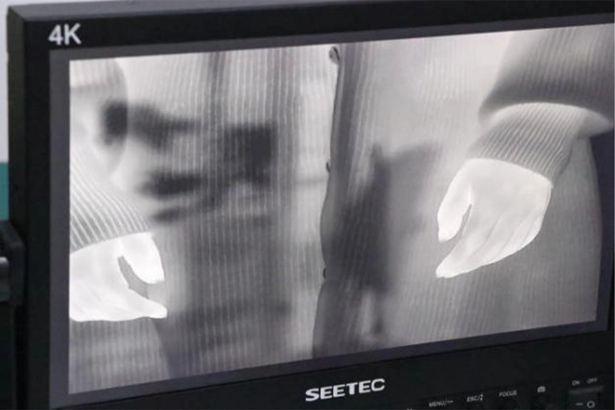
2. Select a uniformly surfaced object to cover the lens or the camera core window portion. Simultaneously, select Background Correction in the software. Click it, wait a few seconds, then remove the object; correction is complete.
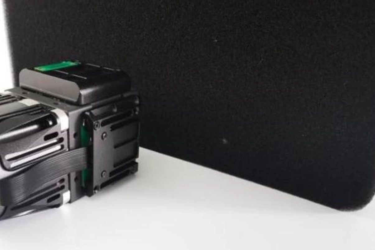
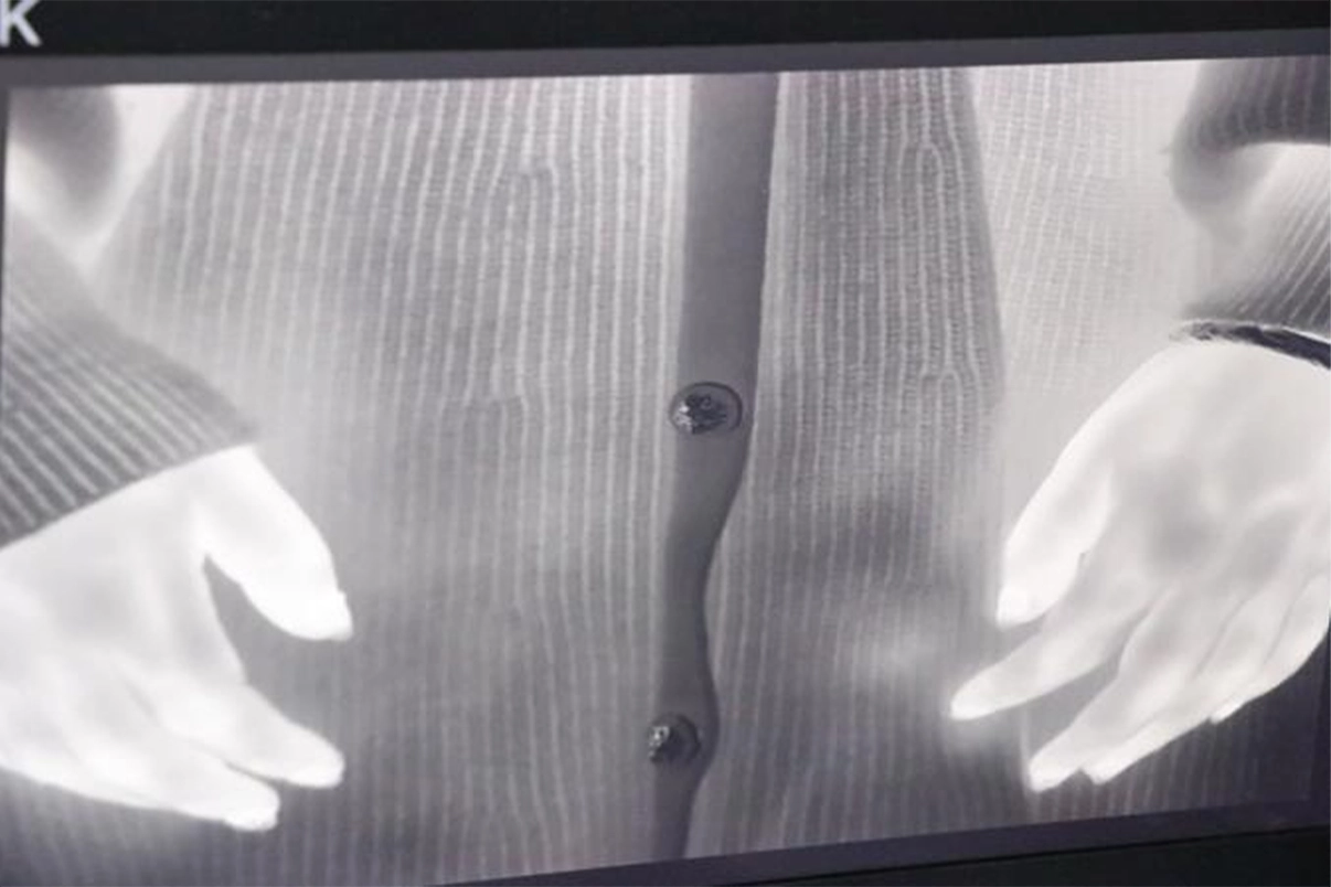
3. Corrected Image
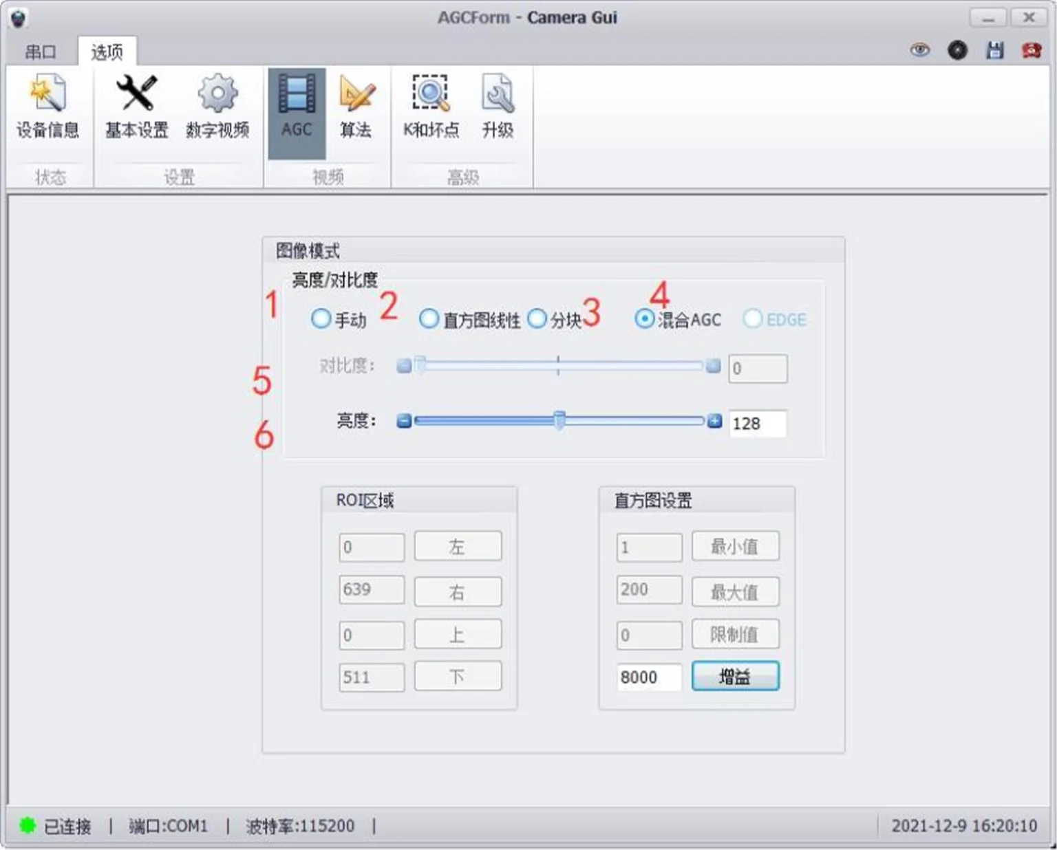
Select AGC mode:
1 Manual;
2 Histogram Linear;
3 Local Histogram Equalization;
4 Hybrid AGC. Different modes have different adjustable parameters.
5 is Contrast Adjustment, adjustable by dragging or manual input.
6 is Brightness Adjustment, adjustable by dragging or manual input.
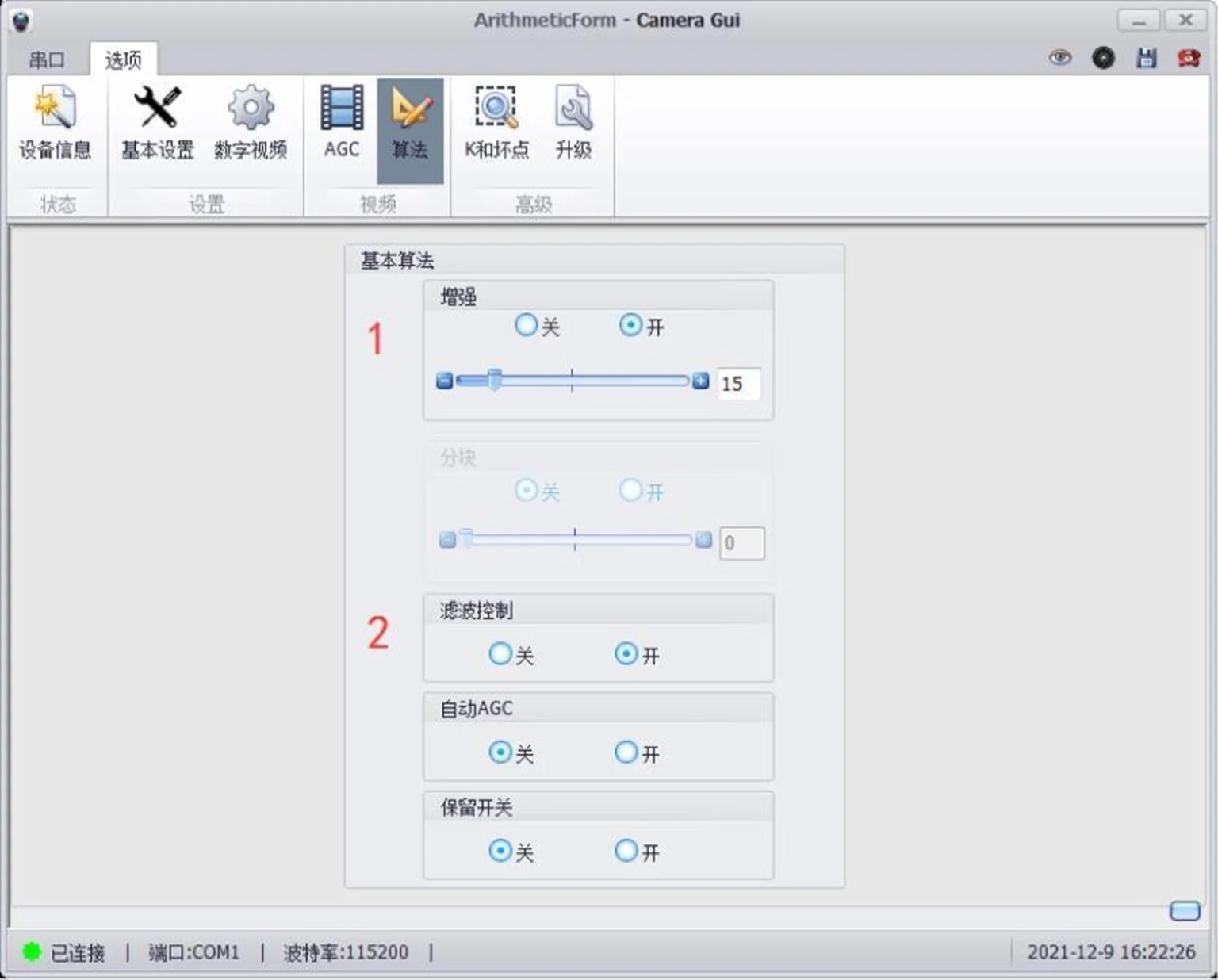
- Image Enhancement Switch (DDE):
Turn image enhancement on or off, adjustable enhancement parameters. - Filter and Algorithm Switch:
Turn filtering and other algorithms on or off
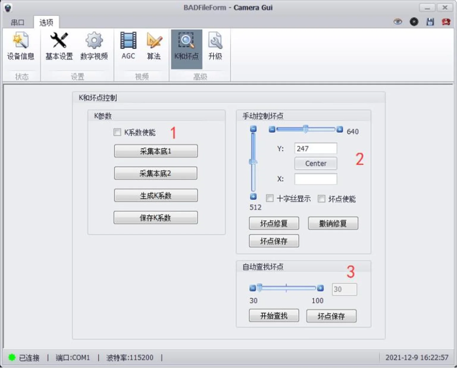
- K Coefficient Generation:
The K Coefficient Enable button controls the K function switch. The Normal Temperature K Coefficient requires two temperature ranges from blackbodies for image calibration. It is recommended that the high-temperature range be between +40℃ and +55℃, and the low-temperature range be between 0℃ and +20℃.Calibration Procedure:
a) Power on and wait for the image to appear normally. In Basic Settings -> Image Mirror, select Normal mode. Enter the K Coefficient page to collect parameters.
b) Place the camera core in front of a blackbody set within the +40℃ to +55℃ range. Click Collect B1 to perform the first parameter collection.
c) Place the camera core in front of a blackbody set within the 0℃ to +20℃ range. Click Collect B2 to perform the second parameter collection (positioning the core similarly as above).
d) Click Generate K Coefficient.
e) Click Background Correction to perform background correction and check the K coefficient effect.
f) If satisfied with the K coefficient effect, click Save K Coefficient to save the parameters.
g) If not satisfied, repeat the above steps.
2. Dead Pixel Replacement
a) Click the Crosshair button to enable the dead pixel crosshair.
b) Use the slider and enter numbers to control the horizontal and vertical coordinates:
X controls the horizontal coordinate, Y controls the vertical coordinate.
c) Click Center to return the crosshair to the screen center.
d) Click the Dead Pixel Enable button to turn dead pixel replacement on/off.
e) Use the dead pixel crosshair to mark the dead pixel at its center. Click the Dead Pixel Repair button to fix it, or click the Undo Repair button to undo the dead pixel repair
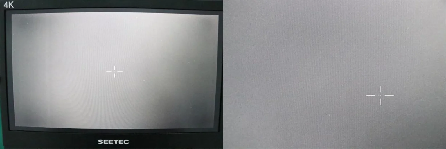
3. Auto Find Dead Pixels
a) Users can activate the Auto Find Dead Pixels function if they find that dead pixels still exist or have increased on the core.
b) Observe a surface with uniform appearance and significant temperature difference. After locating a visible dead pixel, click + or – to fine-tune the position and repair it.
c) Set a matching threshold between 30 and 100, click Start Find to automatically locate dead pixels; the changes take effect immediately.
d) Check if dead pixel replacement was successful. If satisfied, click Save Dead Pixels. Otherwise, repeat the above steps.
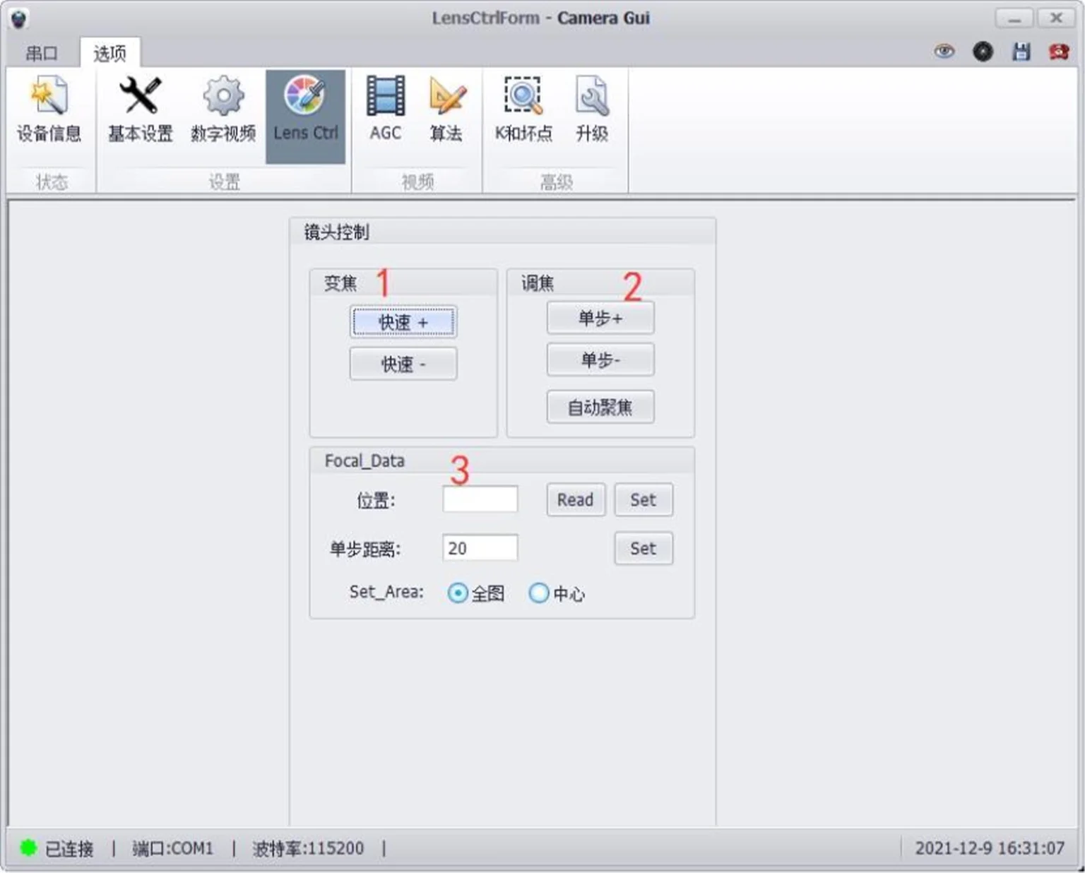
- Quick Adjustment.
- Step Focus: Set step size per single step.
- 3. Set Position.
Q1:What does it mean for the cooling time across the full temperature range to be <7 minutes, and how should we understand MTTF=10000h?
Cooling time across the full temperature range <7 minutes: In the allowed full operating temperature range, it takes no more than 7 minutes for the unit to go from power-on to the detector reaching the rated low-temperature working state.
MTTF 10000h means the average fault-free operating time designed for the cooling components. Vibration, high-temperature environments, and frequent start-stop cycles can all shorten the actual service life of the cooler.
Q2:What is a T2SL (Type-II Class II superlattice) detector? What is the difference from an MCT mercury tellurium detector?
The T2SL Class II superlattice is the third-generation infrared detector technology for artificial superlattice structures of III-V group materials, optimized for mid-wave infrared waves of 3.7-4.8μm.
T2SL advantages: Good material uniformity, low blind spot rate; Dead pixel rate of this movement <0.3%; Lower overall power consumption and smaller size and weight; Good radiation resistance and process consistency;
MCT (Cadmium Mercury Tellurium): High quantum efficiency and high maturity, but poor chemical stability of mercury and limited yield of large arrays.Q3:What are the features of MWIR in target detection?
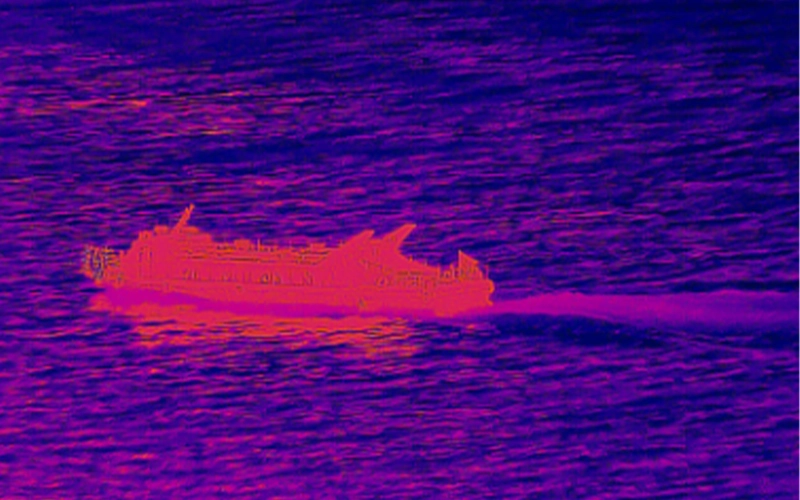
Mid-wave infrared is highly sensitive to temperature differences, making it great at spotting hot targets like engines or missile exhaust. Its strong thermal contrast boosts imaging performance, which makes it really good for precise detection in highly dynamic scenes.
640 X 512 MWIR Cooled T2SL Infrared Camera Module
MWIR1503TCL
MWIR Thermal Cameras Core with T2SL Detector, 15 µm Pixel
Optional accessories – MWIR Lenses
Our Mid-Wave Infrared (MWIR) lens offers a wide range of optical solutions to enhance your thermal imaging system. They are designed to meet a wide range of detection, recognition, and identification requirements . Available as optional accessories, the lineup includes continuous zoom lenses covering ranges from 15‑300mm up to 60‑1200mm with aperture options of f/4.0 or f/5.5 depending on the model.
MW275S
18–275mm EFL, F/5.5 MWIR Motorized Zoom Lens, for 640×512 (15μm) Detector
MW300S
15-300mm EFL, F/4 MWIR Motorized Zoom Lens, for 640×512 (15μm) Detector
MW360S
40-360mm EFL, F/4 MWIR Motorized Zoom Lens, for 640×512 (15μm) Detector
MW550S
30-550mm EFL, F/5.5 MWIR Motorized Zoom Lens, for 640×512 (15μm) Detector
MW600S
30-600mm EFL, F/4 MWIR Motorized Zoom Lens, for 640×512 (15μm) Detector
MW900S
45-900mm EFL, F/4 MWIR Motorized Zoom Lens, for 640×512 (15μm) Detector
MW1200S
80-1200mm EFL, F/4 MWIR Motorized Zoom Lens, for 640×512 (15μm) Detector