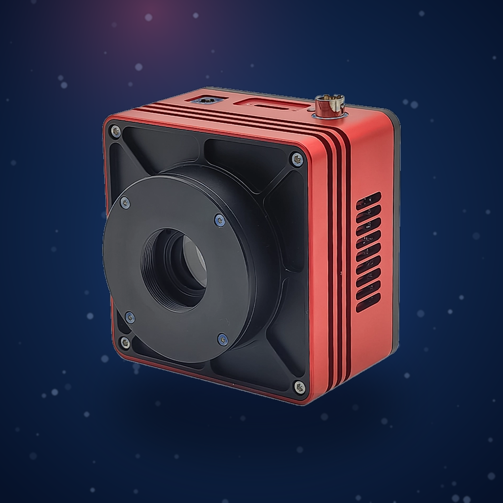
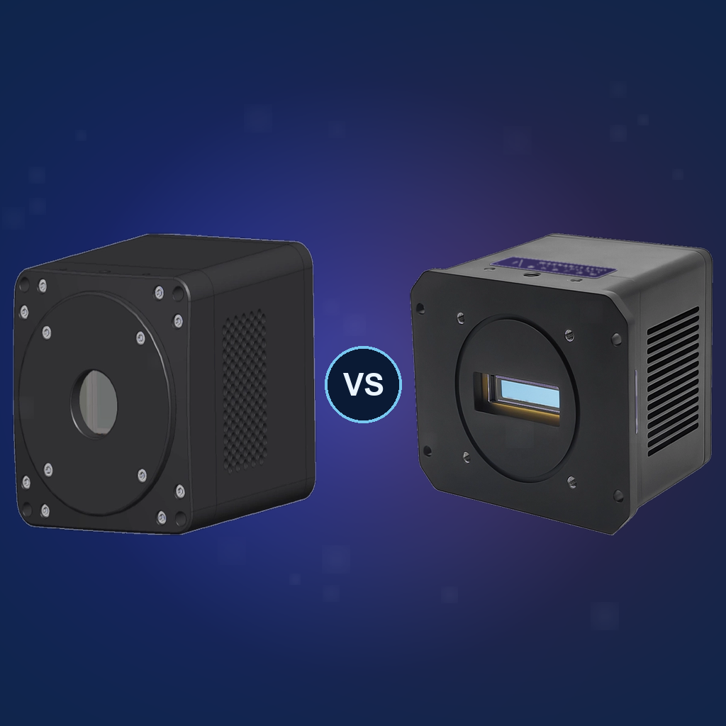
Project Name: Liquid Position Imaging in Opaque Container Using SWIR051AU Camera
Test Date: May 2026
I. Test Objective
To verify the capability of the Attostek SWIR051AU SWIR camera to perform non-contact imaging detection of internal liquid level height through the wall of an opaque plastic tube, and to compare the results with visible-light camera imaging, while evaluating the effectiveness of supplementary light sources and optical filters in improving imaging contrast.
II. Application Background and Principle
2.1 Application Background
In the production processes of chemical, pharmaceutical, food and beverage, and daily chemical industries, liquid level detection is a critical step in quality control. However, many industrial pipelines and containers are made of opaque plastic materials to protect the contents from light exposure or to meet structural strength requirements. Conventional visible-light cameras cannot penetrate such opaque tube walls, and the human eye cannot directly observe the internal liquid level.
2.2 Detection Principle
Most plastics that are opaque in visible light have good transmittance in the short-wave infrared band. Water accounts for the majority of the liquid inside industrial pipelines. In this experiment, water was selected as the internal liquid. Water can absorb infrared light at wavelengths around 1450 nm. When captured by a SWIR camera, water molecules strongly absorb light in this band, resulting in weak reflected signals and appearing as dark areas in the image. In areas without liquid, SWIR light passes through the plastic tube wall and appears as bright areas. The liquid level height can be clearly determined by the boundary between bright and dark regions, enabling non-contact, non-destructive real-time detection. In addition, infrared light sources or infrared filters can be used to enhance the reflection intensity difference between different regions.
2.3 Camera Performance Requirements
- High signal-to-noise ratio (SNR)
- High quantum efficiency (QE), especially near 1450 nm
Specifications of the SWIR051AU camera used in this report:
- Maximum SNR: 52.6 dB
- Quantum efficiency at 1450 nm: approximately 72%
III. Test Equipment and Parameters
| Equipment/Component | Model/Specification |
|---|---|
| SWIR Camera | Attostek SWIR051AU |
| Visible-Light Camera | Attostek VIS028CU3.2-NC |
| Light Source | 1300 nm infrared light source |
| Optical Filter | 1300 nm infrared filter |
| Test Sample | Opaque plastic tube containing water |
| Environmental Conditions | Indoor environment, no special light source except experimental fill light, temperature 25°C |
IV. Test Procedure
- Fix the SWIR051AU camera and adjust the position of the plastic tube so that it is centered in the lens field of view.
- Manually adjust the camera focus and aperture to obtain a clear image.
- Select an appropriate exposure time (manual or automatic mode).
- Capture images with the SWIR051AU camera under the following conditions: no filter and no fill light, with 1300 nm fill light, with 1300 nm filter, and with both 1300 nm filter and fill light.
- Capture a reference image using a visible-light camera (VIS028CU3.2-NC) from the same position.
V. Test Results
5.1 Image Observation Results
- Visible-light camera capture: The plastic tube is completely opaque; the internal liquid cannot be seen, and the image shows only the tube surface.
- SWIR051AU direct capture: The liquid area inside the plastic tube is clearly visible as a dark region, while the area without liquid (the top of the tube) appears as a bright region. The liquid level boundary is clearly distinguishable. In addition, residual liquid above the tube can also be observed with equal clarity.
- With 1300 nm fill light: Overall image brightness is improved, and the contrast between bright and dark areas is enhanced.
- With 1300 nm filter: Light outside the 1300 nm wavelength is filtered out, enhancing the contrast between bright and dark areas.
- With filter + fill light: The best imaging quality is achieved, with a clean background and the most distinct liquid level boundary.
5.2 Quantitative Contrast Analysis
To quantitatively evaluate the discriminative capability of liquid level imaging, contrast was calculated using the following formula:
Contrast = (I_max − I_min) / Gray Scale Range
where I_max and I_min are the average gray values of the liquid-free area and the liquid area, respectively, and the gray scale range is 255 for 8-bit images.
| Capture Condition | Average Gray Value (Liquid Area) | Average Gray Value (Plastic Tube) | Calculated Contrast |
|---|---|---|---|
| SWIR051AU direct capture | 103.1 | 157.9 | 0.21 |
| With 1300 nm fill light | 77.8 | 138.5 | 0.24 |
| With 1300 nm filter | 58.1 | 103.2 | 0.18 |
| With 1300 nm filter and fill light | 49.9 | 123.7 | 0.29 |
VI. Result Analysis
- Function verification: The SWIR051AU camera can effectively penetrate the opaque plastic tube, clearly image the liquid inside, and accurately display the liquid level height and liquid residue. The liquid-filled portion appears as a dark area, while the rest appears bright, with a clearly distinguishable liquid level boundary.
- Performance: The camera has high signal-to-noise ratio, a clean image background, and stable bright-dark boundaries at the liquid level, meeting industrial quality inspection requirements.
- Optimization recommendation: In practical applications, it is recommended to use both the 1300 nm filter and a fill light of the same band simultaneously to achieve the highest contrast, thereby improving detection stability.
VII. Conclusion
The Attostek SWIR051AU SWIR camera can effectively penetrate opaque plastic tube walls and achieve non-contact imaging detection of liquid level height inside pipelines. Through imaging experiments under different conditions, it was found that the best liquid level image contrast is achieved with the combination of 1300 nm fill light and 1300 nm filter.
The SWIR051AU SWIR camera, with its high signal-to-noise ratio and quantum efficiency, can well meet the application requirements for liquid level detection and liquid residue inspection inside opaque plastic tubes in industrial settings.