2K 12.5μm Pixels 900-1700nm SWIR Camera
| Features |
| The spectral response range covers 900–1700 nm. |
| 2048×1 resolution,12.5 μm pixel size |
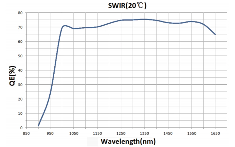
| Quantum efficiency reaches 70% at 1550 nm |
| Global shutter, high-speed acquisition |
| Hardware ROI & external triggering |
| 512MB cache Model-Dependent |
| CE/FCC Cerifcation,Multi-platform SDK |
The SDK supports development languages such as C/C++, C #/VB.net, Python, Java, etc,
Third-party support including LabVIEW, MATLAB, Micro-Manager, DirectShow, and TWAIN.
| Model | SWIR2048L3A-CL80K |
| Sensor Type | InGaAs SWIR line-scan image sensor |
| Spectral Range | 900–1700 nm |
| Resolution | 2048 pixels (2048 × 1) |
| Pixel Size | 12.5 µm × 12.5 µm |
| Sensor Size | 25.6 mm |
| Frame Rate | 79K @ 2048×1 |
| Memory | 512 MByte |
| Quantum Efficiency | 70% @ 1550 nm |
| Conversion Gain | 6.1 e-/ADU (GAIN = 1) |
| Dynamic Range | 64.1 dB (GAIN = 1) |
| Readout Noise | 60.4 e- (GAIN = 1) |
| Full Well Capacity | 96.4 ke- (GAIN = 1) |
| Maximum SNR | 49.8 dB (GAIN = 1) |
| Exposure Time Range | 1us-1s |
| Shutter Type | Global Shutter |
| Data Interface | CameraLink Full |
| Digital I/O | 1 channel of optically isolated input, 1 channel of optically isolated output |
| Data Format | 14 bit |
| Cooling performance | -20°C TEC cooling (ambient temperature 20°C) |
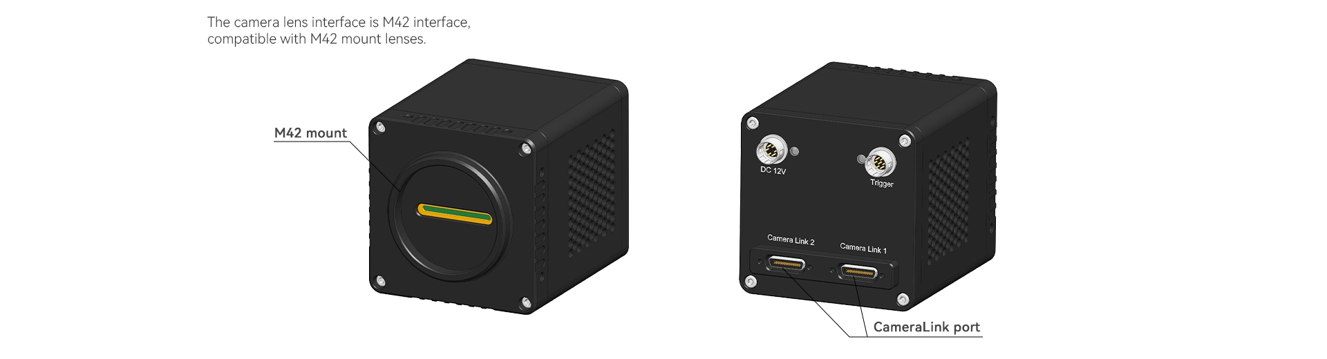
| Lens Mount | M42 |
| Dimensions | 68 mm × 68 mm × 90.3 mm |
| Weight | 485 g |
| Software | AttosView/SDK |
| Operating Temperature | -40 °C to 70 °C |
| Storage Temperature | -40 °C to 70 °C |
| Humidity | 20%-80%, non-condensing |
| Certification | CE, FCC |
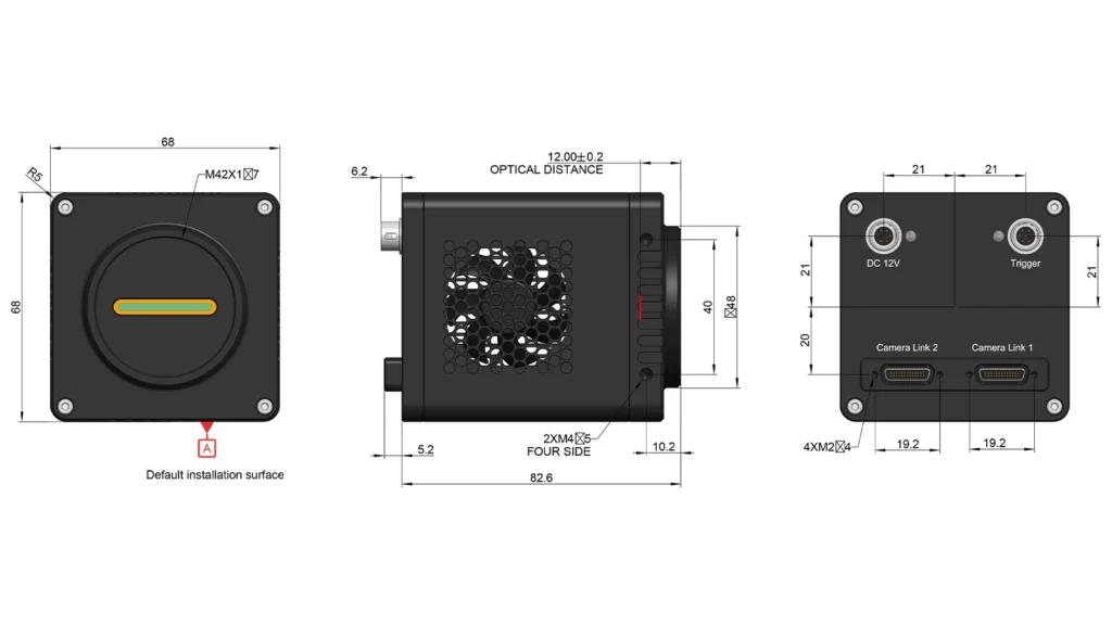
| Table1: USB port, GigE port, CL port refrigerated camera pin signal definitions | |||||
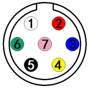 |
Color | Pin | Signal | Description of the signal | |
| White | 1 | GDN | Direct-coupled signal ground | ||
| Red | 2 | 12V | 12VDC power input | ||
| Blue | 3 | OPTO_GND | Opto-isolated signal ground | ||
| Yellow | 4 | DIR_GPIO0 | Direct-coupled General Purpose I/O (Software configurable input/output) (line2) | ||
| Black | 5 | DIR_GPIO1 | Direct-coupled General Purpose I/O (Software configurable input/output) (line3) | ||
| Green | 6 | OPTO_IN | Opto-isolated input signal (line0) | ||
| Pink | 7 | OPTO_OUT | Opto-isolated output signal (line1) | ||


The electrical characteristics of the opto-isolated output (external voltage 5V, external resistor 1K) are shown in Table 2.
| Table 2: Opto-isolated output signal’s electrical characteristics | ||
| Parameter name | Parameter notation | Parameter value |
| Output logic low | VL | 742mV |
| Output logic high | VH | 4.134V |
| Output rise time | TR | 4us |
| Output fall time | TF | 1.8us |
| Output rise delay | TDR | 12us |
| Output fall delay | TDF | 2us |
The output of the corresponding output current and VL when using different voltages and resistors in externalcircuit are shown in Table 3.
| Table 3:Opto-isolated output logic’s low levels parameters | |||
| External voltage | External resistor | VL | Output current |
| 3.3V | 1KΩ | 510mV | 2.82mA |
| 5V | 1KΩ | 742mV | 4.31mA |
| 12V | 2.4KΩ | 795mV | 4.68mA |
| 24V | 4.7KΩ | 850mV | 4.97mA |
1. Line2/line3 is set as input pin
Logic 0 input level: 0~0.6VDC (DIR_GPIO0/DIR_GPIO1 pins)
Logic 1 input level: 2.0~24VDC (DIR_GPIO0/DIR_GPIO1 pins)
Maximum input current: 25mA
When the input level is between 0.6V and 2.0V, the circuit action state is uncertain, please avoid the input voltage range working in this range.
To prevent damage to the GPIO pins, please connect the pin GND first, and then input voltage to the Line2 pin.
Input rise delay (TDR): 0.02us
Input fall delay (TDF): 0.02us
2. Line2/line3 are set as output pins
The maximum current allowed through this pin is 25mA.
The external pull-up voltage is 5V, the pull-up resistor is 1KΩ, and the GPIO is configured to output the logic level and electrical characteristics as shown in Figure 4.


When the ambient temperature is 25 degrees Celsius, the relationship between the external voltage, resistance and low-level voltage output is shown in Table 4.
| Table 4:Non-isolated output Logic’s low level parameters | ||
| External voltage | External resistor | VL(GPIO) |
| 3.3V | 1KΩ | 0.11V |
| 5V | 1KΩ | 0.167V |
| 12V | 2.4KΩ | 0.184V |
| 24V | 4.7KΩ | 0.385V |
| Table 5: Non-isolated output electrical characteristics | ||
| Parameter name | Parameter notation | Parameter value |
| Output rise time | TR | 0.08us |
| output fall time | TF | 0.02us |
| Output rise delay | TDR | 0.1us |
| Output fall delay | TDF | 0.04u |
ascamsdk support a variety of APIs, including: Native C/C++,.NET/C#/VB.NET, Python, Java, DirectShow, Twain, LabView, Matlab, etc. Compared with other APIs, Native C/C++ API as a low-level API is characterized by using pure C/C++ development without relying on other runtime libraries. The interface is simple and the control is flexible.
AttosTek provides extensive third-party software support for its UV-Vis cameras and SWIR cameras, facilitating rapid integration and use in various development environments. This includes SDK and demo programs for LabVIEW and MATLAB, as well as DirectShow drivers, Micromanager, and TWAIN SDK drivers. These features enable seamless compatibility with mainstream development environments and third-party software, greatly simplifying the workflow for system integration and secondary development.
|
AttosView Recommended System Requirements |
|
|
Operating System |
Microsoft® Windows® XP / Vista / 7 / 8 /10 /11(32 & 64 bit), Mac OSX, Linux |
|
Processor (CPU) |
≥3.0 GHz Intel Core i5 or Higher |
|
Memory (RAM) |
≥8 GB |
|
Hard Drive |
NVMe Solid State Drive (SSD) |
|
Graphics Card |
Dedicated Adapter with ≥256 MB RAM |
|
Motherboard |
USB 3.0 (-USB) Cameras: Integrated Intel USB 3.0 Controller or One Unused One Unused PCle3.0*16 Slot |
|
Connectivity |
Internet Connectivity for Driver Installation |
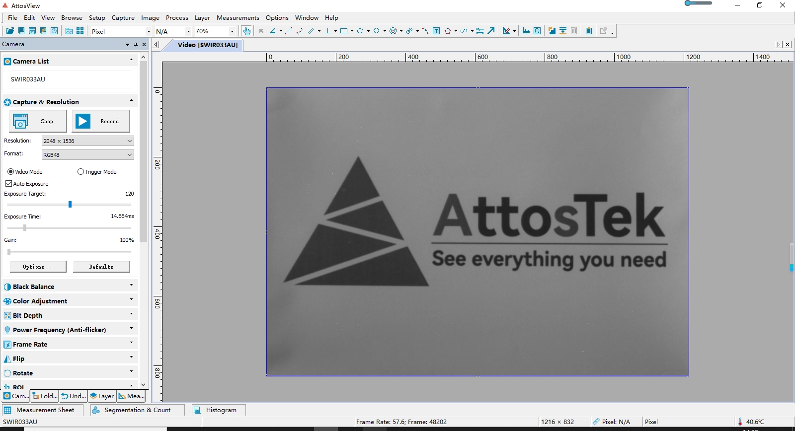
|
Function |
Function description |
|
Operating mode |
Operating mode: video mode or trigger mode |
|
Denoise |
The camera hardware incorporates denoise |
|
Automatic exposure |
Automatic exposure or manual exposure function |
| Gain |
HG, MG, LG 3 gain modes |
|
Frame rate |
Supports precise frame rate control |
|
ROI |
Supports single-zone ROI with a maximum frame rate of 8000fps after ROI |
| Flip |
Supports Vertical/horizontal flip |
| Custom dark field correction |
The hardware supports up to 12 groups of user-defined dark field correction image functions |
|
Timestamp function |
Timestamps can be turned on or off. After the timestamp function is enabled, the low 8bits of 1-8 pixels, 9-16 pixels, and 17-24 pixels will be modified to: 0-7: frame number; 8-15: Frame time; 16-23: trigger signal count |
|
Firmware update |
Supports firmware online update |
|
Pipette function |
Supports the display of the gray value of the mouse pixel position |
|
Histogram display |
Supports histogram display and statistics |
| Plane line function |
Supports the function of viewing surface data |
|
Regional gray statistics |
Support the average gray statistics function of user-defined areas |
|
Cooling system |
1) The cooling system of the camera uses a built-in TEC cooling chip for the sensor, with external heat dissipation structure and fan auxiliary heat dissipation, the working temperature can be adjusted to a specific value, the effective cooling temperature can be lower than the ambient temperature of 40℃, and the high-efficiency cooling system ensures extremely low dark current level; |
Q1:What's the imaging principle and hardware support for line-array 900–1700nm band photovoltaic/silicon wafer inspection?
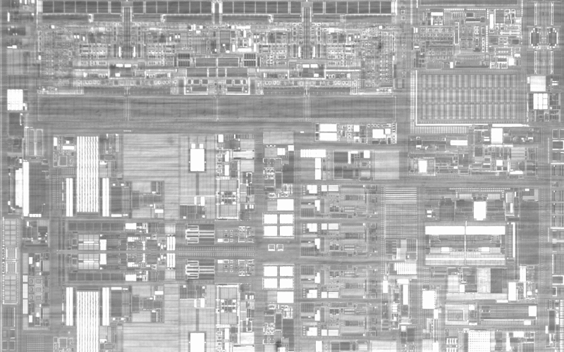
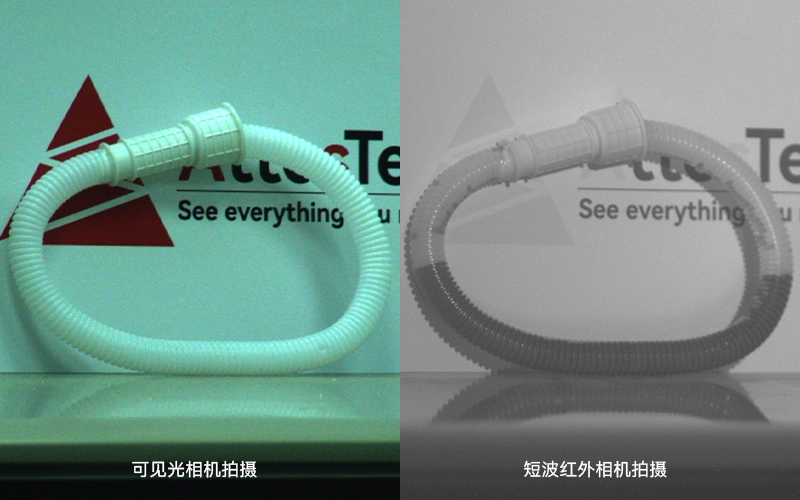
Principle of Silicon Wafer Inspection Imaging: Silicon material is transmissive in the short-wave infrared above 900nm, while visible light can only detect surface scratches. Using a line scan push mode with a conveyor moving at a constant speed, infrared reflection signals of the entire silicon wafer or battery are collected line by line to capture subsurface defects like hidden cracks, voids, and impurities. Different silicon media have stable differences in infrared reflection grayscale, allowing automated batch defect detection.
This camera has a 2048-pixel single-line array with 12.5μm pixels, peak quantum efficiency of 70% at 1550nm, and excellent infrared sensitivity. With a full-frame ultra-high line frequency of 79kHz, it suits high-speed photovoltaic production lines for continuous line scanning. It features -20°C PID constant temperature TEC cooling to suppress dark current during long scans, keeping the line’s grayscale stable over time. The global shutter with 1μs ultra-short exposure prevents motion blur in fast-moving wafers. It has 512MB large onboard memory to ensure no frame loss at 79kHz continuous data stream, and CameraLink Full high-speed transmission, synchronized with a photoelectric-coupled IO conveyor encoder, ensures precise line-by-line data acquisition.
Q2:Compared to the same series of area array cameras, what are the different use scenarios for the line scan SWIR2KBCL-80K?
Linear arrays are specifically designed for continuous strips, rolls, and long production line sweeping, with 79kHz high-speed line-by-line scanning, making them suitable for 24/7 uninterrupted online inspection of sheets and films.
Area array cameras are better for static samples and single workpiece snapshots and can’t handle continuous imaging on infinitely long conveyor belts, so the two setups are totally incompatible on production lines.
Q3:How does the M42 mount work with original C-mount short-wave lenses, and what shooting scenarios are suitable for each focal length?
M42 mount can be adapted to the full range of C-mount SWIR lenses:
6/8/12mm short focal: wide plastic films, full-tray fruits and vegetables, continuous scanning;
25/35/50mm mid-long focal: narrow silicon wafers, precision films, high-precision scanning for tiny defects;
100mm long focal: long-distance large-area photovoltaic panels, inspection of long strip materials;
Full range F1.4~F2.0 large apertures, giving higher signal-to-noise ratio on weak, low-reflection materials.
2048 Line Scan Cameras for imaging & machine vision
SWIR2KBCL-80K
2048 Line Scan SWIR Cameras, 12.5μm Pixels, CameraLink Interface
Optional accessories – lenses
To meet the diverse application demands of short-wave infrared (SWIR) imaging, Attostek offer a series of high-performance SWIR lenses. This lineup covers focal lengths from 6mm to 100mm and features a wide aperture range of F1.4 to F2.0 as standard, ensuring high signal-to-noise ratio and superior image quality even in low-light conditions. Users can flexibly select different models based on field of view, working distance, and resolution requirements, providing high sensitivity and versatile scene adaptability for SWIR cameras in applications such as security surveillance, industrial inspection, and scientific research.
SWIR0618C
6mm Focal Length, f1.8, C-Mount SWIR Camera Lenses
SWIR0814CL
8mm Focal Length, f1.4, C-Mount SWIR Camera Lenses
SWIR1214C
12mm Focal Length, f1.4, C-Mount SWIR Camera Lenses
SWIR1614C
16mm Focal Length, f1.4, C-Mount SWIR Camera Lenses
SWIR2514C
25mm Focal Length, f1.4, C-Mount SWIR Camera Lenses
SWIR3514C
35mm Focal Length, f1.4, C-Mount SWIR Camera Lenses
SWIR5014C
50mm Focal Length, f1.4, C Mount SWIR Camera Lenses
SWIR10020C
100mm Focal Length, f2.0, C-Mount SWIR Camera Lenses