Experiment Name: Interference Signal Imaging Using the UVISI114BU High-Sensitivity Visible-Light Camera
Experiment Date: August 2025
I. Test Task
Task Description:
Fluorescence emitted by excitons at different spatial positions may possess a certain degree of spatial coherence. Spatial coherence can be calculated by observing the interference fringes of exciton emission.
Application Background:
By observing the interference fringes of a Michelson interferometer, the coherence length of exciton emission can be calculated, providing a measure of interactions between excitons. Exciton emission with a relatively long coherence length can be used as a laser light source.
II. Experimental Process and Data
Test Equipment and Main Parameters:
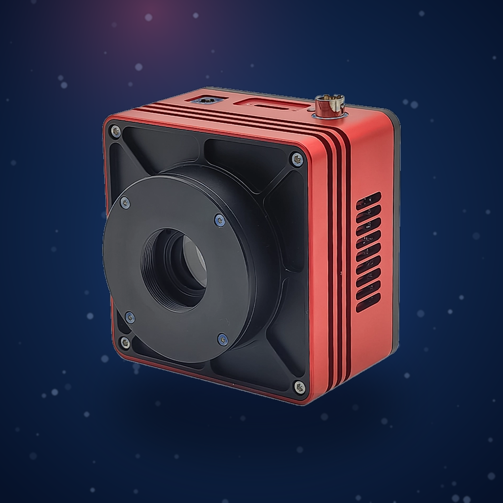
- Camera: Attostek UVISI114BU
- Light Source: 532 nm continuous-wave semiconductor laser
Experimental Process / Data:
- Use the 532 nm laser to align the optical path, adjust the two arms of the Michelson interferometer to complete collimation, and ensure the outgoing beams are perfectly overlapped.
- Observe the beam spot on the camera and fine-tune the mirror on one arm until the two spots are completely overlapped; at this point, interference fringes become visible on the camera.
- Filter out the excitation laser, adjust the delay line of one arm of the interferometer, and observe the interference fringes on the camera to locate the clearest position, which is the zero optical path difference point.
- Adjust the delay line and capture interference fringes at different optical path differences.
III. Experimental Results and Analysis
Using the 532 nm laser, clear interference fringes were observed. The fringe spacing was consistent with theoretical calculations. The camera demonstrated stable performance and relatively high sensitivity.