16 MP 9 μm Pixels 200-1100nm sCMOS Camera
| Features |
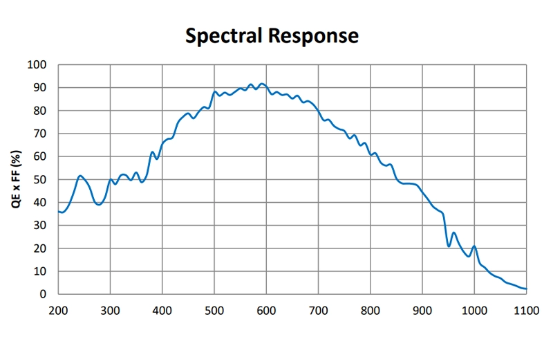
| The spectral response range covers 200–1100 nm. |
| 16MP resolution, 9 μm pixel size |
| Roller Shutter /Global Reset |
| 12-bit ADC / 16-bit combined HDR |
| Supports external I/O trigger control |
| 1024 MB (8 Gb) large capacity cache |
| CE/FCC Cerifcation,Multi-platform SDK |
The SDK supports development languages such as C/C++, C #/VB.net, Python, Java, etc,
Third-party support including LabVIEW, MATLAB, Micro-Manager, DirectShow, and TWAIN.
| Model | UVISI0916BUCL, UVISI0916BUCL-GPS |
| Sensor model | GSENSE4040BSI sCMOS |
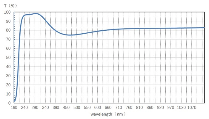
| Spectral range | 200nm – 1100nm |
| Color Type | Monochrome |
| pixel size | 9 µm x 9 µm |
| Target size | 3.2″ |
| Resolution | 4096 x 4096 |
| Frame Rate | 20 fps @ 4096×4096 (USB3); 23 fps @ 4096×4096 (Camera Link); |
| Bit Depth | 8/12/16bit |
| Memory | 1024MB (8Gb) |
| Conversion gain | 12bit: 0.35e-/DN(HCG 12x) 10.42e-/DN(LCG 3x) |
| Dynamic Range | 12bit: 55.0dB(HCG 12x) 62.4dB(LCG 3x) |
| Read noise | 12bit: 4.06e-(HCG 12x) 35.61e-(LCG 3x) |
| Full well charge | 12bit: 1.30ke-(HCG 12x) 39.2ke-(LCG 3x) |
| SNR | 12bit: 30.7dB(HCG 12x) 45.9dB(LCG 3x) |
| Sensitivity | 26.58 V/(lux-s)@550nm |
| Dark current | 0.15e-/s/pix |
| QE | 90% @ 550nm |
| Dark signal inhomogeneity | 0.5e |
| Optical signal inhomogeneity | 0.20% |
| Exposure time range | 12us-3600s |
| Gain Range | 1x – 12x |
| Shutter mode | Rolling shutter / Global reset |
| Binning mode | Software 2×2, 3×3. 4×4 |
| Data interface | USB3.0 / CameraLink |
| Digital I/O | 1 channel of optically isolated input, 1 channel of optically isolated output, 2 channels of non-isolated input/output port |
| Data Format | RAW8 / RAW12 / HDR16 |
| Cooling temperature difference | 40°C below ambient temperature |
| Power supply | DC19V 4.74A power supply |
| Power consumption | TEC ON:58.7W;TEC OFF:16.2W;TEC OFF + CameraLink Only:8.2W |
| Working temperature | -30 ~ 45 ℃, |
| Storage temperature | – 40 ~ 60 ℃ |
| Humidity | 0-95% |
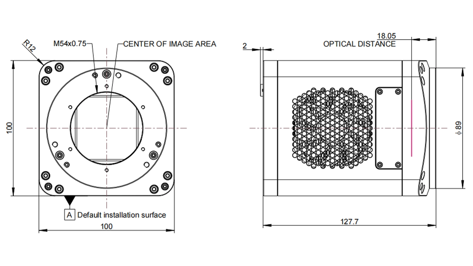
| Size | 100*100*127.7 |
| Weight | 1317g |
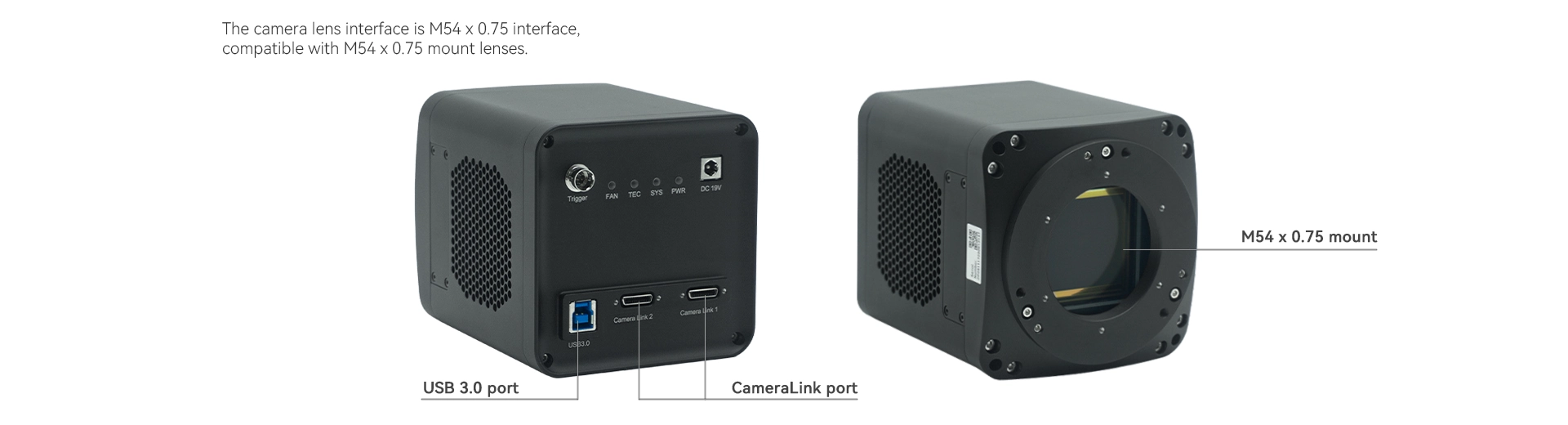
| Lens mount | M54 x 0.75 |
| Software | AttosView , LabView, MATLAB,Third-Party Software etc |
| Operating system | Windows, Linux |
| Certification | CE, FCC |
| Parameter | Specification |
| Dimension | 100*100*127.7mm |
| Weight | 1317g |
| Lens interface | M54 x 0.75 |
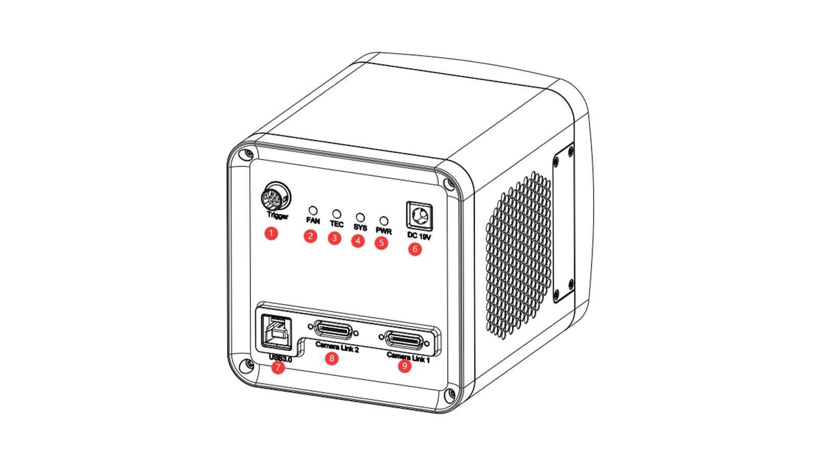
| Item | Specification |
| 1 | Trigger 7PIN |
| 2 | FAN LED indicators |
| 3 | TEC LED indicators |
| 4 | System LED indicators |
| 5 | Power LED indicators |
| 6 | DC 19V power port |
| 7 | USB 3.0 port |
| 8/9 | CameraLink port |
| Table1: USB port, GigE port, CL port refrigerated camera pin signal definitions | |||||
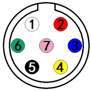 |
Color | Pin | Signal | Description of the signal | |
| White | 1 | GDN | Direct-coupled signal ground | ||
| Red | 2 | 12V | 12VDC power input | ||
| Blue | 3 | OPTO_GND | Opto-isolated signal ground | ||
| Yellow | 4 | DIR_GPIO0 | Direct-coupled General Purpose I/O (Software configurable input/output) (line2) | ||
| Black | 5 | DIR_GPIO1 | Direct-coupled General Purpose I/O (Software configurable input/output) (line3) | ||
| Green | 6 | OPTO_IN | Opto-isolated input signal (line0) | ||
| Pink | 7 | OPTO_OUT | Opto-isolated output signal (line1) | ||


The electrical characteristics of the opto-isolated output (external voltage 5V, external resistor 1K) are shown in Table 2.
| Table 2: Opto-isolated output signal’s electrical characteristics | ||
| Parameter name | Parameter notation | Parameter value |
| Output logic low | VL | 742mV |
| Output logic high | VH | 4.134V |
| Output rise time | TR | 4us |
| Output fall time | TF | 1.8us |
| Output rise delay | TDR | 12us |
| Output fall delay | TDF | 2us |
The output of the corresponding output current and VL when using different voltages and resistors in externalcircuit are shown in Table 3.
| Table 3:Opto-isolated output logic’s low levels parameters | |||
| External voltage | External resistor | VL | Output current |
| 3.3V | 1KΩ | 510mV | 2.82mA |
| 5V | 1KΩ | 742mV | 4.31mA |
| 12V | 2.4KΩ | 795mV | 4.68mA |
| 24V | 4.7KΩ | 850mV | 4.97mA |
1. Line2/line3 is set as input pin
Logic 0 input level: 0~0.6VDC (DIR_GPIO0/DIR_GPIO1 pins)
Logic 1 input level: 2.0~24VDC (DIR_GPIO0/DIR_GPIO1 pins)
Maximum input current: 25mA
When the input level is between 0.6V and 2.0V, the circuit action state is uncertain, please avoid the input voltage range working in this range.
To prevent damage to the GPIO pins, please connect the pin GND first, and then input voltage to the Line2 pin.
Input rise delay (TDR): 0.02us
Input fall delay (TDF): 0.02us
2. Line2/line3 are set as output pins
The maximum current allowed through this pin is 25mA.
The external pull-up voltage is 5V, the pull-up resistor is 1KΩ, and the GPIO is configured to output the logic level and electrical characteristics as shown in Figure 4.


When the ambient temperature is 25 degrees Celsius, the relationship between the external voltage, resistance and low-level voltage output is shown in Table 4.
| Table 4:Non-isolated output Logic’s low level parameters | ||
| External voltage | External resistor | VL(GPIO) |
| 3.3V | 1KΩ | 0.11V |
| 5V | 1KΩ | 0.167V |
| 12V | 2.4KΩ | 0.184V |
| 24V | 4.7KΩ | 0.385V |
| Table 5: Non-isolated output electrical characteristics | ||
| Parameter name | Parameter notation | Parameter value |
| Output rise time | TR | 0.08us |
| output fall time | TF | 0.02us |
| Output rise delay | TDR | 0.1us |
| Output fall delay | TDF | 0.04u |
ascamsdk support a variety of APIs, including: Native C/C++,.NET/C#/VB.NET, Python, Java, DirectShow, Twain, LabView, Matlab, etc. Compared with other APIs, Native C/C++ API as a low-level API is characterized by using pure C/C++ development without relying on other runtime libraries. The interface is simple and the control is flexible.
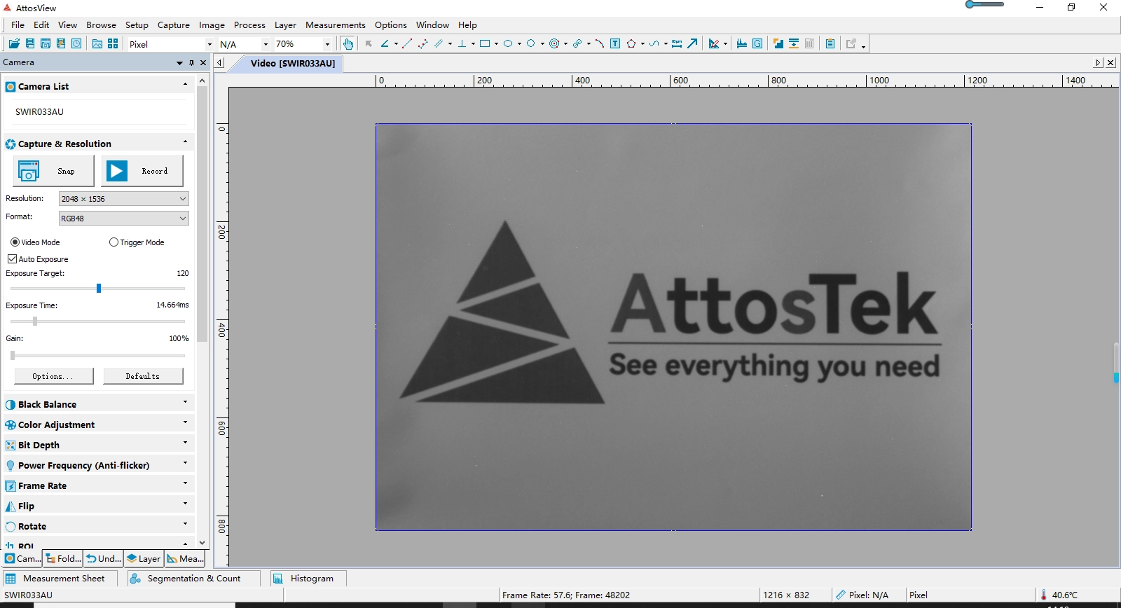
AttosTek provides extensive third-party software support for its UV-Vis cameras and SWIR cameras, facilitating rapid integration and use in various development environments. This includes SDK and demo programs for LabVIEW and MATLAB, as well as DirectShow drivers, Micromanager, and TWAIN SDK drivers. These features enable seamless compatibility with mainstream development environments and third-party software, greatly simplifying the workflow for system integration and secondary development.
|
AttosView Recommended System Requirements |
|
|
Operating System |
Microsoft® Windows® XP / Vista / 7 / 8 /10 /11(32 & 64 bit), Mac OSX, Linux |
|
Processor (CPU) |
≥3.0 GHz Intel Core i5 or Higher |
|
Memory (RAM) |
≥8 GB |
|
Hard Drive |
NVMe Solid State Drive (SSD) |
|
Graphics Card |
Dedicated Adapter with ≥256 MB RAM |
|
Motherboard |
USB 3.0 (-USB) Cameras: Integrated Intel USB 3.0 Controller or One Unused One Unused PCle3.0*16 Slot |
|
Connectivity |
Internet Connectivity for Driver Installation |
Q1 : What are the advantages of this camera series for astronomical observation imaging?
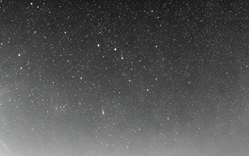
Astronomical observations of deep space stars have very few photons, so long exposures on the scale of hours are needed. When multiple telescopes or array cameras are used, unified timestamps are required for star map matching.
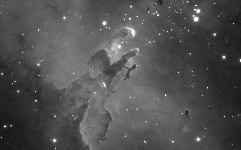
This camera has an ultra-low dark current of 0.15 e⁻, with no background haze even during 3600s long exposures. Its 3.2-inch large sensor provides a super wide field of view covering the sky area. With 1GB of cache, it can store all-night images. The GPS model offers UTC time synchronization at the microsecond level, so multi-camera frame timing is fully aligned, eliminating timing errors in array acquisition.
Q2 : What's the difference between the GPS-equipped model and the regular model?
The VIS0916BUCL-GPS model integrates a GPS module on top of the standard version, allowing precise UTC time synchronization. The time sync accuracy for multi-camera setups can reach microseconds.
Selection recommendation: If you need multi-camera synchronized capture (like astronomical observatories, distributed arrays, or synchrotron experiments) → go for the -GPS model; for single standalone use (regular lab research) → the standard model is fine.
Q3 :Can Linux/ARM embedded systems collect data independently without a host PC?
Sure. The SDK provides precompiled libraries for various architectures and complete examples, allowing you to develop Windows-free embedded spectrometers and small automatic astronomical observation devices.
16 MP 9 μm Pixel Back-illuminated sCMOS High-Sensitivity Camera
UVISI0916BUCL
16 MP BSI sCMOS Camera with 9μm Pixels, USB3.0 & CL Dual-Interface
UVISI0916BUCL-GPS
16 MP BSI sCMOS Camera with 9μm Pixels (Equipped with GPS version), USB3.0 & CL Dual-Interface
Optional accessories – lenses
AttosView offers an optional YLGD series continuous zoom optical system for visible light cameras, designed specifically for high-precision imaging scenarios. The YLGD series continuous zoom optical system series provides multiple focal length options and is suitable for various professional applications such as security surveillance, industrial vision inspection, and scientific observation, ensuring excellent image clarity, operational flexibility, and environmental adaptability. For inquiries, please contact sales@attostek.com .